
A small team building a portable air-quality display often starts with a sensor module on a desk, powered continuously over USB. The next request sounds simple: put it in a case, add a battery and let someone carry it between rooms. But a sensor with an internal heater changes both the power budget and what the user should expect after switching it on.
We looked at this question with a GraftSense MG811 module: a heated, solid-electrolyte CO2 sensor on a carrier board that conditions its signal. The module documentation and the manufacturer references describe the sensor well. They do not establish battery runtime, enclosure temperature or a dependable cold-start waiting time. Those become separate questions when a desk demonstration turns into a portable prototype.
Start with the load that stays on
The metal sensor can contains a heater as well as sensing electrodes. The heater establishes the operating condition; the electrodes produce a small voltage related to CO2 concentration. Reading that voltage less often does not, by itself, reduce the heater's power consumption.
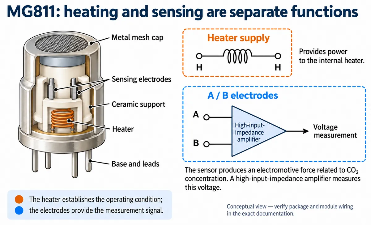
That distinction matters if the application only updates a display once a minute. The processor can spend most of that minute asleep while the heater keeps drawing power. A low software sampling rate tells you little about total runtime until you know which parts remain powered. The cutaway above is conceptual; it does not reproduce the exact internal geometry or physical pin positions.
Match the specification to the actual part
Before calculating runtime, confirm which document belongs to the component you bought. The parameter sheet supplied with the module lists a 6.0 ± 0.1 V heater supply, 30 Ω ± 5% heater resistance at room temperature, about 200 mA heater current and a nominal heater consumption of about 1.2 W. The MG811 manual currently served by Winsen, version 1.2 dated March 10, 2015, instead lists 850 ± 120 mW on page 3, and its heater resistance and current entries also differ.
These are conflicting reference values, not a measured range for your particular board. Use the documentation confirmed for the purchased probe and carrier, then measure the assembled unit. Do not average the two figures or assume that a matching model name settles the difference.
For scale, suppose a planning exercise uses a battery with 7.4 Wh of nominal energy and a continuously powered 1.2 W heater. Dividing energy by power gives about 6.2 hours for the heater alone, before power-conversion losses, the processor, radio, display or unusable battery capacity. This is an illustrative calculation from one specification, not a runtime prediction or a battery recommendation.
The practical measurement belongs at the battery input of the complete prototype. Record the operating mode alongside the current: starting up, waiting for a reading, updating the screen and sending data may be different loads. That record tells you whether changing the display interval will make a meaningful difference, or whether the sensing approach dominates the budget.
Check which voltage belongs to which part
A heater specification is not automatically the supply specification of the carrier board. The manufacturer's package drawing separates the heater terminals (H) from the measurement terminals (A and B). Follow the documentation for the exact assembled module before connecting power; the heater's nominal 6 V value is not an instruction to apply 6 V to a board connector marked VCC.
For comparison, DFRobot's SEN0159 documentation describes a different MG811 module with a 5 V supply and an onboard circuit that boosts the heater supply. That shows why the probe and the carrier must be identified separately. It does not establish the input requirements or protection of the GraftSense board.
At the integration stage, obtain the carrier revision and supply requirements along with the sensor name. If the portable enclosure is already being designed, leave room to evaluate airflow and to measure temperatures in the assembled arrangement. Component drawings cannot tell you how warm a finished handheld case will become.
A fast response curve does not mean an instant reading after power-up
The manufacturer publishes a graph showing the sensor's response when gas exposure changes. That graph is useful for understanding the sensor's behavior under its stated conditions. It is not a test in which an unpowered portable device is switched on and immediately produces a trustworthy room reading.
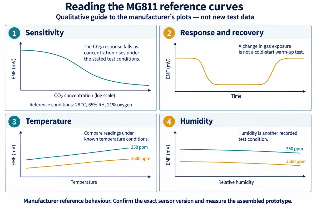
Three timings need separate names: conditioning after storage or first use, settling after a normal power-up, and response to a change in gas concentration while operating. The Winsen manual includes storage-dependent ageing guidance on page 5. That guidance should not be silently converted into a universal delay for every power cycle. The curves above are manufacturer reference behavior without digitized data or a calibration equation, not measurements of a portable prototype.
Builders run into this distinction directly. In a DFRobot forum question from February 25, 2023, a user asked whether the warm-up requirement applied every time or only initially. The replies gave inconsistent advice about the initial duration. The thread documents the confusion; it does not provide a validated startup rule.
If saving power means switching the heater off between readings, establish that the exact device supports the intended operating cycle and test how it recovers. Do not copy a duty cycle from a different CO2 sensing technology. A system that saves energy while displaying an unsettled value has changed the measurement, not merely optimized the battery.
Make readiness part of the user trial
For a first portable trial, define what the person holding the device should see before a valid reading is available. A clear "warming up" state can be more useful than immediately displaying a number whose meaning is uncertain. The transition to a usable reading needs evidence for the actual hardware and conditions, rather than an arbitrary delay chosen to make the interface feel quick.
Plan repeated starts using the selected probe, power circuit, software and enclosure. Record elapsed time, raw output, supply behavior and relevant environmental conditions against a suitable reference. Decide in advance what counts as a stable, acceptable reading for the intended application. These are proposed validation steps; we have not run them on this module.
The resulting decision may be to keep continuous external power for the first trial, accept a shorter portable session, or evaluate a sensing approach documented for the desired power cycle. Each choice is easier to explain once the brief names the required runtime, the acceptable waiting time and the purpose of the measurement. None of them requires pretending that a working desk demonstration already answers all three.