
Imagine a handheld guide that changes its display when someone turns it upright, or an interactive object that responds when it is tipped to one side. You may not need precise motion tracking. You need the device to recognize a few useful positions without changing its mind every time a hand trembles.
A three-axis accelerometer can handle that first version. On our bench we connected a GraftSense ADXL345 module to a GraftPort-RP2040 board and printed readings in MicroPython. That is a starting point for orientation sensing, not yet a finished tilt-controlled interface.
So the useful question is specific: can you recognize the positions your users need, after the object has settled? Answer that before promising that the same sensor will track a fast gesture, a moving vehicle or an exact angle.
A stationary sensor still has something to measure
An accelerometer reports acceleration along three axes. When the module is resting, gravity shows up across those axes according to its orientation. Turning it changes how that roughly 1 g total is distributed. The reading does not drop to zero because you stopped moving it.
This is a common stumbling block. In an Arduino discussion from April to May 2014, a builder expected rotating the board to produce the same peak readings as waving it. For an interface the difference matters: tipping an object and shaking it are different inputs.
The module has its axes marked on the board. Keep that orientation information when you mount it in the enclosure. The user's "left" is a direction on the finished object, not automatically the sensor's positive X.
For inclination sensing, gravity needs to dominate the measurement. Movement adds acceleration, and smoothing the readings slows the response. Analog Devices explains this trade-off in AN-1057 by Christopher J. Fisher. A device that changes mode after being held still is a much simpler first experiment than continuous motion control.
An accelerometer alone also does not give a compass heading. Turning a level object around its vertical axis does not change how gravity falls across the axes, so it cannot be told apart the way tipping can. Decide which movement actually belongs in the interaction before choosing the sensing arrangement.
Wire it, then confirm it is the right chip
We used the I2C0 connector: data on GP4, clock on GP5. The module runs its sensor at 3.3 V logic with its own pull-ups; the board's regulator is not a reason to connect arbitrary 5 V signal levels.
- SDA: RP2040 GP4
- SCL: RP2040 GP5
- Power and ground: matching connector functions on module and controller; check your actual board
- I2C address: 0x53 or 0x1D, depending on the module's address selection
The ADXL345 chip also has a CS pin that must be high for I2C. On this module it is already tied to the 3.3 V rail. Our example program created a GP22 output for a generic driver, but that does not mean the four-wire module needs a fifth wire to GP22.
MicroPython uses seven-bit I2C addresses, so start with 0x53 and 0x1D rather than copying a read/write address byte from a protocol diagram. A response at an address only proves that something answered; the ADXL345 device-ID register should return 0xE5. This read-only check does that for the pins above. We have syntax-checked it but not run it on this hardware, and it does not put the sensor into measurement mode:
from machine import I2C, Pin

bus = I2C(0, sda=Pin(4), scl=Pin(5), freq=100_000)
found = bus.scan()
for address in (0x53, 0x1D):
    if address in found:
        device_id = bus.readfrom_mem(address, 0x00, 1)[0]
        print(hex(address), hex(device_id), device_id == 0xE5)
What our test program actually showed
We installed an ADXL345 driver package (an MIT-licensed driver credited to fanday) and ran a loop that printed X, Y and Z every half-second. The install command we used named version 1.0.0, while the archive we kept was 1.0.1. Record which version you use; they may not be identical.
Readings are in mg, meaning milli-g, one thousandth of gravitational acceleration, not milligrams. The driver selects full-resolution mode at a ±16 g range with about 3.9 mg per count. That describes the digital scale, not the accuracy of an assembled tilt sensor.
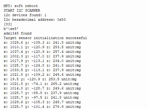
The scan found address 0x53 and device ID 0xE5. Most X readings were around 1,000 to 1,040 mg, with smaller Y and Z values. That is consistent with the X axis lying close to vertical, although we did not measure the actual angle for comparison.
One line instead reported X as 19.5 mg. We cannot tell whether the board moved, a read was inconsistent or something else happened. Keep exceptions like that in the record: what this shows is communication and changing readings, not a validated level meter or a stability figure.
Fix the reading path before adding an angle display
Two details in the driver we used deserve attention before you build behavior on these numbers. It created its own I2C bus at 10 kHz even though the main program scanned at 400 kHz. And it read the six axis-data bytes in separate register transactions while setting a 100 Hz output rate.
The manufacturer recommends a single multi-byte read for the axis registers and limits the output rate according to bus speed. Reading all six bytes together avoids assembling one sample from different updates. Review the bus speed and data rate together before using the driver for angle calculations; more decimal places will not fix an inconsistent input stream.
The headline specifications need the same care. "13-bit" applies to the full-resolution ±16 g setting; it is not 13-bit angular accuracy. Offset, noise, mounting alignment and the operating mode all affect the result. The very large shock figure in an absolute-maximum table is a survival limit, not a measurement range. Builders asking for hundredths of a degree from this part often report angles that wander while the device sits still.
Test the interaction in the enclosure
For the next prototype, start with two or three clearly separated positions rather than a continuously changing degree readout. A handheld guide might only need to tell "lying flat" from "held upright." That is a proposed use; we have not implemented it.
Mount the sensor as it will sit in the enclosure, record readings in each intended position, and repeat with different users. Add a transition band so tiny changes near a boundary do not keep switching the interface. Then choose how long a position must last before it is accepted, based on the delay users will tolerate.
Include the movements between positions. Picking the object up, setting it down and bumping the cable can briefly produce readings that look like a new orientation. Log those events alongside the displayed state. If the interaction needs a fast response during continuous motion, revisit the sensing and processing approach rather than assuming a stationary test covers it.
The next milestone is small and observable: someone picks up the assembled object, puts it in each intended position and understands its response. Once that works reliably, you can decide whether a finer angle estimate adds anything useful.