
A prototype does not always need a touchscreen. If someone only needs to see a count, a remaining time or one measurement, four large digits can be easier to use than a page of menus. The catch is that four digits leave little room to explain themselves.
Before choosing the display, write down exactly what the user should see: the smallest and largest values, any minus sign, the decimal point, the unit and what happens when data is missing. A module that can show 1234 may still be wrong for 12.34, a clock-style 12:34 or a useful error message.
On our bench we drove two four-digit LED modules on GraftSense carriers from a Raspberry Pi Pico running MicroPython: one built on a TM1637, one on an HT16K33. Comparing them separates three choices that are easy to confuse: the visible display, the electrical interface and the software that formats the value.
Choose the punctuation before the driver
Seven-segment digits can form numbers and a limited set of letter-like shapes. Decimal points and a colon are extra LEDs, and whether they exist depends on the actual display package and its wiring. The driver chip's name does not tell you which punctuation is present.
That is the problem in a 2018 Arduino forum thread: a builder can light the clock colon but not the apparent decimal points, and replies distinguish clock displays from versions with individually wired points. No library can light an LED the package does not contain.
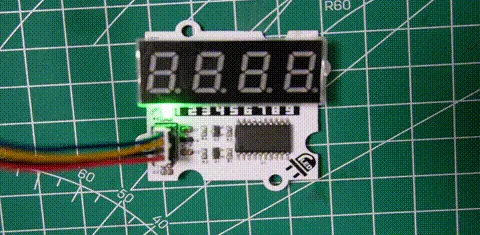
Our TM1637 module showed a clock-style display with a central colon, while its schematic named a different display arrangement with a decimal-point connection. Treat that as a variant to check on the board you actually have.
The HT16K33 was clearer. Our program requested 8.888, and the display showed the point after the first digit.
Two signal wires do not mean the same interface
The TM1637 plugged into the Pico carrier's connector labeled I2C0, but the software drove GP5 (CLK) and GP4 (DIO) as ordinary GPIO. The connector made wiring convenient; it did not make the TM1637's two-wire protocol standard I2C.
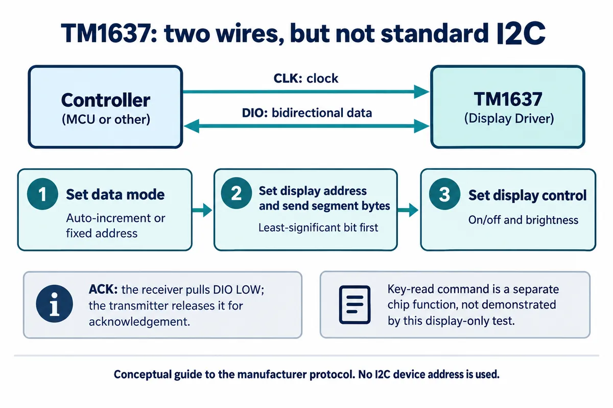
That matters when you add sensors. Do not expect the TM1637 to show up in an address scan, or assume it can share an I2C bus because its cable fits.
The HT16K33 does use hardware I2C, on GP4 (SDA) and GP5 (SCL) at 400 kHz. Our scan found it at 0x70, which is fixed on this 20-pin carrier; other packages and boards offer different address choices.
Power needs its own check. The later HT16K33 schematic revision specifies a common-cathode display, a 5 V driver supply and level shifting to a nominal 3.3 V controller interface; some descriptions of the board called it common-anode, so use the matching schematic and fitted part. On the TM1637 board, the regulator part number and the labeled rail did not agree. Verify the actual board before treating supply and logic levels as settled.
What the two tests did
The TM1637 test cycled through brightness levels, short text, pairs of numbers, integers, hexadecimal values, temperature-shaped examples, scrolling and raw segment patterns. The "temperature" values were constants in the program; no sensor was involved. The terminal only recorded the program starting, while the display itself showed the characters changing. Keep both kinds of evidence, because a terminal message cannot tell you whether the segments lit correctly.
The HT16K33 driver we used, from deshipu-micropython-ht16k33 (MIT), works differently: you change a memory buffer, then call show() to send it to the module:
seg7.fill(False)
seg7.text("1234")
seg7.show()
That lets you prepare several digit changes before one visible update. Forget the final call and nothing changes on the display. Our program went on to 8.888, a hexadecimal example, 9876, a run of brightness settings and a final clear.
Both chips handle the continuous scanning that keeps the digits lit. Your application still decides when the value changes. Those are different timing jobs: a countdown updates when its value changes, while the driver keeps refreshing the segments in between.
Decide what happens when a value does not fit
With four positions, formatting is a product decision. A minus sign takes a position; decimal precision uses positions on both sides of the point. A reading that fits during a bench demo may stop fitting when it goes negative or crosses a boundary.
The TM1637 driver we used (derived from Mike Causer's micropython-tm1637, MIT) silently limited its number helper to -999 through 9999, so -1234 displayed as -999. That is fine in a demonstration and misleading if a user reads it as a measurement. Check the range in the application and show an explicit out-of-range state instead.
Our TM1637 string helper also rejected a literal decimal point, and its colon option set one segment bit rather than handling punctuation in general. The HT16K33 files had their own limits: in the seven-segment mapping we used, a space selected the zero glyph, and the colon helper overlapped a digit's buffer location. Test every formatting case you intend to use, not just the ones the demo covered.
For a device with one fixed unit, a unit printed on the front panel may be clearer than an abbreviated scrolling message. If the same number can mean several things, the user needs a visible way to tell the current mode. If that takes long explanations, a text or graphical display may fit better.
Keep missing data distinct from a real zero. A counter at zero, a sensor that has not reported yet and a display that lost communication are three different states. Pick a pattern the module can actually render, explain it to users and verify it. Never leave an old reading on screen as if it were current.
Try the display where someone will use it
Brightness settings are useful, but their count is not a readability rating. These modules expose eight levels (TM1637) and sixteen (HT16K33). We did not measure luminance, viewing angle, window losses or outdoor performance, so more settings is not evidence that one module is easier to read.
A Reddit discussion about sunlight-readable seven-segment displays shows why the application matters: the person needed a changing speed value with tenths, not a static sign. Visibility and update rate have to be decided together.
For your prototype, place the actual module behind the intended window and look at it from the expected distance, angle and lighting. Include zero, the largest value, a minus sign, the decimal point and the proposed fault state. Ask someone who did not write the software what each state means. That trial can expose a missing unit or an ambiguous point long before you commit to a front-panel design.