
A fluorescent label, painted object or display piece can look striking under a handheld UV light. Turning that effect into an interactive exhibit raises different questions: will the whole object light evenly, can one button control it, and what happens when the LEDs sit inside an enclosure for a full demonstration?
These are integration questions for design, education and exhibition teams. In a July 2026 BudgetLightForum thread, a cabinet builder lit a display with several UV flashlights, and other members asked about a shared switch and power source and how diffusion changed the result. That is the step from an attractive effect to a usable assembly.
On our bench we drove a GraftSense four-LED UV matrix module from a GraftPort-RP2040 with an external adjustable supply. That shows lamp control. It is not a tested fluorescent exhibit, and several component and software details had to be resolved before the circuit could serve as a build recipe.
Start with the object you want people to see
Choose the actual paint, label or material before designing around a wavelength on a module listing. The first question is whether the intended feature stands out under the intended viewing conditions. The lamp's visible purple glow measures neither its UV output nor the fluorescence you want to reveal.
For a camera-based version, the light source is only one part of the optical path. Hamamatsu's explanation of fluorescence detection optics modules describes excitation LEDs, optical elements and detectors working together. A hobby lamp array provides none of the rest. The cover, filter, camera and sample have to be evaluated as a combination.
Our module's description said four nominally 365 nm LEDs, while its component documentation named an NTD3528U1 with a different package and current rating. Confirm the fitted LED from the actual build record before choosing a replacement, operating current or optical filter. The manufacturer's spectrum and viewing-angle curves explain what the specification means; they are not measurements of the assembled board, and a typical viewing angle does not guarantee even light across your object.
Understand the control path before changing it
Four LED-and-resistor branches sit in parallel, and an AO3400 N-channel MOSFET switches their common return. The microcontroller drives the MOSFET gate through the DOUT pin; the lamp supply provides the LED current. Despite its label, DOUT is the module's control input.
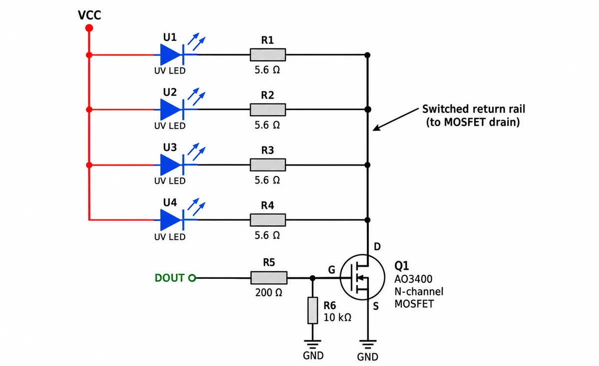
The 10 kohm pull-down keeps the gate low when nothing drives it. It is not an interlock and does not guarantee the light stays off under every firmware fault. Giving each branch its own resistor is the right topology, because LED forward voltages differ and a single shared resistor after parallel LEDs shares current poorly. The topology is right; the 5.6 ohm value still has to be checked against whichever LED is actually fitted.
The records disagree on that. The module description said about 0.3 A and a 3030 package; the NTD3528U1 datasheet gives 150 mA continuous absolute maximum at 25 °C and a 3.5 × 2.8 mm package. An absolute maximum is a limit, not a design target, and we could not establish which specification applies to our assembly.
As a rough check with the described 5 V supply, a 3.4 V LED drop and 5.6 ohm: (5 − 3.4) / 5.6 ≈ 0.286 A per branch while conducting, before switch and other losses. That is arithmetic from assumptions, not a measurement. It is why confirming the part and current comes before copying a supply setting.
Read the demonstration as a sequence, not an output specification
Our wiring notes named AIN0, the connection table listed pin 6, and the program used pin 26. Trace the connector's control line to the processor before assigning a GPIO; a photo will not settle it.
The test program initialized the driver, switched on, set a brightness value, switched off, then toggled on and off with pauses. Reading the driver package's code changed how that sequence should be described. Its on() method writes 32766 on the 16-bit PWM scale, about 50% duty, and set_brightness(512) writes 32799, also about 50%. The "full" and "half" messages printed by the program therefore did not compare full and half output.
The driver's state value is a software flag, not a light sensor, and changing brightness does not update it, so it can disagree with the commanded PWM. For an exhibit controller, keep three things apart: the requested setting, the electrical output, and the light that reaches the object.
Our video of the board switching shows the sequence ran. It does not establish irradiance, brightness linearity, material response or a safe viewing distance.
Test the enclosure and the repeated-use pattern together
The program carried a warning about rapid heating in prolonged operation. Lowering PWM duty reduces average heating, but the current during each on-pulse stays the same; the fitted LED's pulse limits, resistor dissipation and board temperature still need checking. The NTD3528U1 datasheet allows 200 mA pulsed only at 0.1 ms or less and 1/10 duty or less.
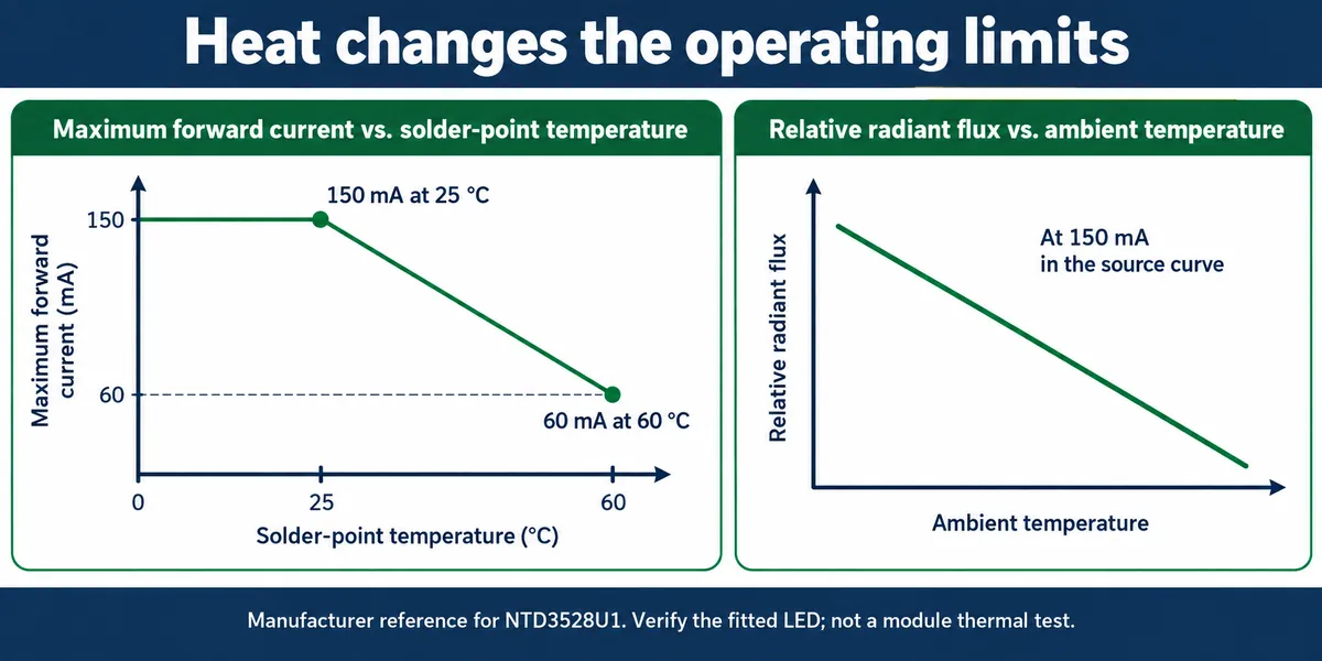
That is why the thermal question cannot wait until the enclosure is finished. Build the optical test around a fixed sample position and a repeatable viewing or camera setup. Compare the intended effect with the lamp off and on, then repeat with the proposed window or diffuser fitted. Lock the camera settings if images are part of the evaluation; automatic exposure can make two different outputs look alike.
Plan how people will encounter the light at the same time. The FDA's ultraviolet radiation overview explains that UVA can damage skin and that UV exposure can affect the eyes, and the LED maker warns against looking into the source. Shielding, access control and an exposure assessment belong in the design. Neither the purple color nor a short software timer makes it safe.
Define what the prototype needs to prove
For a fluorescent exhibit, a useful next test is whether the chosen feature stays clearly visible at the intended distance, through the real window, over the planned demonstration cycle. Record the lamp setting, sample position, ambient light and temperature with each result. A photo of four glowing LEDs cannot answer those questions.
Keep the claim narrow until the evidence grows. Nothing here demonstrates curing, disinfection, authenticity detection or plant-growth effects, and a working fluorescence display would not prove any of them either. The target is not a brighter lamp but a repeatable effect inside a usable assembly.