
If you are building an interactive exhibit, a small flame-sensor board looks like an easy way to make an object respond to light. A lighter brings the demonstration to life. Then you move the prototype near a window, and it starts reacting on its own. Before adjusting the software, it helps to understand what the board is actually sensing.
The problem is common. An Arduino Forum user in September 2019 reported a flame sensor that triggered in sunlight. The thread does not establish a tested cure, but it does name the design problem: a light-sensitive component cannot tell you where the light came from.
On our bench we connected a GraftSense PT334 flame-sensor module to a GraftPort-RP2040 controller board, read its outputs in MicroPython and brought a lighter toward the detector. This note covers what that setup showed and what to check before building this kind of trigger into an interactive object. It is an optical-input prototype, not a design for a fire alarm or burner controller.
Start with the light, then choose the threshold
The detector is a phototransistor: received light changes the current through it. The manufacturer's datasheet for the TONYU DY-PT334-6B lists a nominal peak response at 940 nm, in the near infrared. Its response covers a band of wavelengths. It does not identify a signature that belongs only to flames.
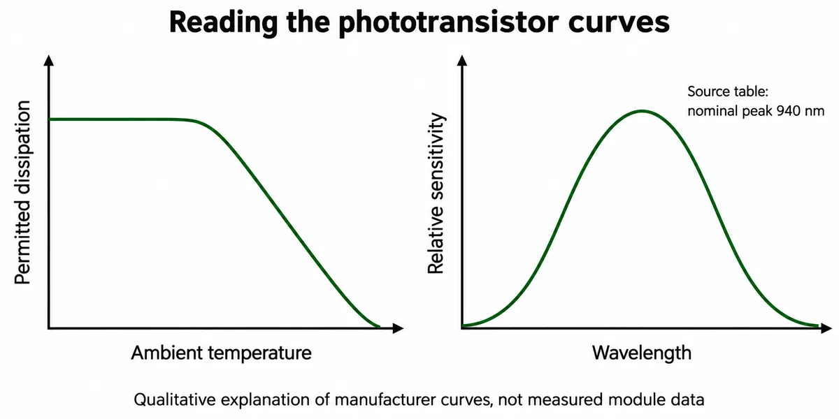
That matters near windows and other infrared sources. If unwanted light reaches the detector strongly enough, the board responds even though the event you wanted never happened. Moving a sensitivity control changes when the board switches; it does not teach the detector to recognize a flame.
Two outputs from one detector
The module offers two ways to observe the response. AOUT carries a changing voltage. DOUT carries a high or low state, decided by an LM393 comparator, a part that compares two voltages. In this circuit the phototransistor pulls the analog signal lower as it receives more light, and the comparator compares that signal with a reference set by the adjustable resistor R1. When the analog signal falls below the reference, DOUT goes low.
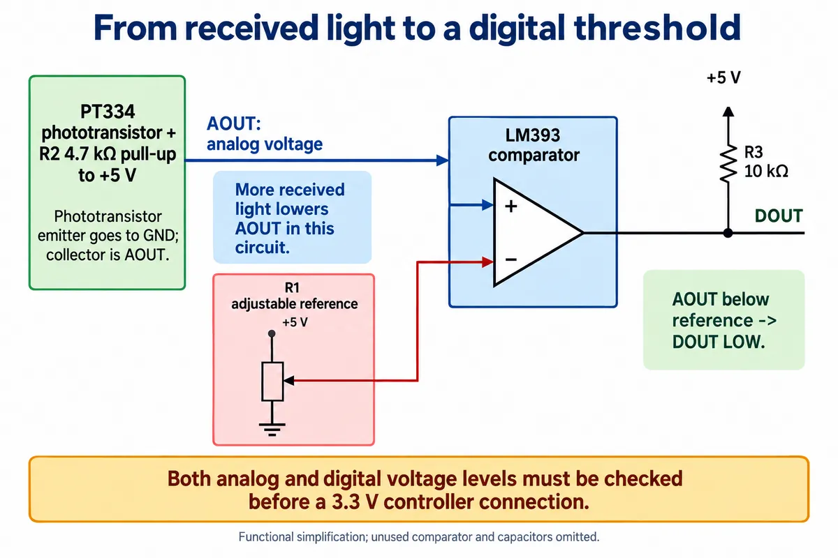
Use the analog value to learn what changes in the room, then decide whether a single switching threshold gives enough separation between the intended input and the background. This assumes the comparator inputs stay within their permitted operating range; turning R1 to either extreme is not a substitute for checking that range.
On the board, LED2 is the power indicator and LED3 lights when DOUT sinks current. When adjusting R1, the useful observation is whether the analog reading and the digital state change together.
Check the signal levels before connecting a 3.3 V controller
We connected the module with a four-wire cable to the carrier's AIN0 connector. The program assigned the analog input to GP26 and the digital input to GP19.
Resolve one electrical detail before copying this onto another board. The module runs from 5 V, derives AOUT from that supply and pulls DOUT up to 5 V. Check how the carrier conditions both signals before they reach a 3.3 V controller. A matching connector does not establish compatible signal levels, and a software display of "3.30 V" does not establish that the input was limited to that voltage.
The LM393 has an open-collector output. The module's resistor supplies the high level when the comparator is not pulling the line low. Changing a software pin setting cannot turn that 5 V pull-up into a 3.3 V signal.
What the MicroPython program showed
Our driver creates a sensor object with the two pin numbers and a callback, a function that runs after an input event. Enabling it sets up falling-edge detection on the digital pin, while the main loop reads the analog voltage once a second. The callback prints a detection message and the loop prints a voltage. These are two different observations, not two independent confirmations that a flame exists.
The voltage is calculated as read_u16() / 65535 * 3.3. That explains why a full-scale reading prints 3.30 V. It is a conversion using an assumed reference, not a measurement of the supply, a calibration result, or proof that a higher input voltage was absent.
The console log from the lighter test showed repeated 3.30 V readings and a run of detection messages, and also this:
RuntimeError: schedule queue full
The driver schedules work after each input event, and MicroPython documents that this queue is finite. The log shows that events reached the software, but the event handling did not stay clean. It does not show whether the burst came from optical variation, threshold chatter, electrical noise or a combination. This was a partly working demonstration, not an error-free endurance test.
We also found a mismatch to fix before relying on the status query. The circuit and interrupt configuration use an active-low trigger, but is_flame_detected() converts the raw pin value directly to a Boolean, so it returns false when the pin is low. Because the demonstration printed from the callback, a convincing terminal message coexisted with a reversed status method. We found this by reading the code, not by a separate hardware test.
Turn the demonstration into a useful interaction
For an exhibit, first decide what counts as one action. Should one approach trigger one animation, or should the object stay active while the light is present? That choice determines whether the application needs a stable state, a single event or a timed rearm. Printing every falling edge can produce many actions from one physical interaction.
Next, compare the intended input with the conditions visitors will actually create: room lighting, daylight through a window, viewing angle and the final opening in the enclosure. Record the analog signal alongside the digital state. A hood or a different orientation may reduce unwanted light, but those changes need checking in the intended setting. If wanted and unwanted inputs still overlap, a tighter software threshold alone will not separate them.
Adding remote visibility does not change this. A hobby project on Hackster sends a flame-module state to an online dashboard; that extends where the signal can be seen, not what caused it.
For some creative projects the better decision is to change the interaction. Enock Mecheo's digital-candle proposal uses a microphone to detect blowing toward an animated candle. It is a proposal, not a verified product, but it asks the right question: does your experience need a real flame, or only a familiar gesture?
Our bench setup got as far as a physical module, an analog reading and recorded input events. The next prototype should establish the conditions under which one intended action produces one predictable response.