
You have a radar module that can report a fall, and a phone that can display the result. Before turning that demonstration into a room-monitoring product, there is a harder question: will it distinguish the event you care about from ordinary activity in the place where it will be installed?
On our bench we built a fall-detection prototype from a GraftSense R60AFD1 millimeter-wave radar carrier, a GraftPort-RP2040 board running MicroPython and an HC-08 Bluetooth module, mounted it overhead and watched the fall-status message change on a phone. The build also left some configuration questions unresolved. Together, these show what a team can learn from a first prototype, and what the next test needs to establish.
Start with the area you need to monitor
A radar's largest sensing footprint is not automatically its useful fall-detection area. The supplier separates movement, stationary presence and fall detection. Someone walking at the edge of the room may be detectable even where the module cannot reliably classify a fall.
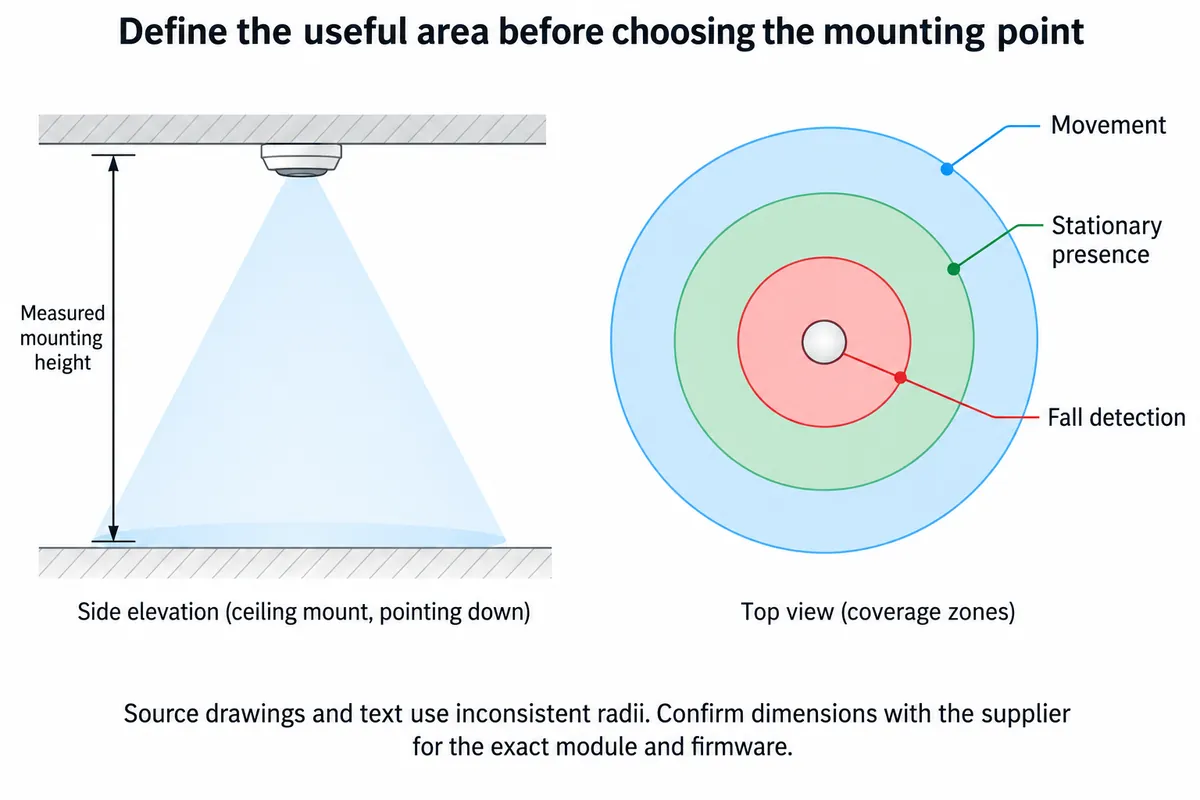
The installation references we worked from gave conflicting radii between text and drawing. Use a diagram like this to understand the relationship between the areas, then obtain dimensions for the exact module and firmware revision. Do not mix one revision's specifications with another's.
This matters to the product concept. A small bathroom, a bedroom containing a bed, and a room shared by two people present different detection tasks. Decide which situation your prototype is meant to cover before deciding that one ceiling-mounted module is enough.
There is a concrete customer problem behind that distinction. In a Seeed community discussion from 2022 to 2023, a builder using another radar reported false alarms with two people, missed events near a bed and alarms when sitting down. The thread does not establish those behaviors for the R60AFD1, but it gives useful scenarios to investigate rather than assuming a successful demonstration settles the question.
Keep the physical setup in the record
The phone gave us a way to watch messages away from the development computer. That is a local demonstration link, not evidence of a complete remote alert service.
We mounted the assembly vertically at about 2 m. However, the configuration readout reported an installation-height setting of 240 cm, while a later configuration snippet set 200 cm. A photograph cannot settle that discrepancy. A repeatable test needs the measured physical height and the value read back from the radar, recorded together.
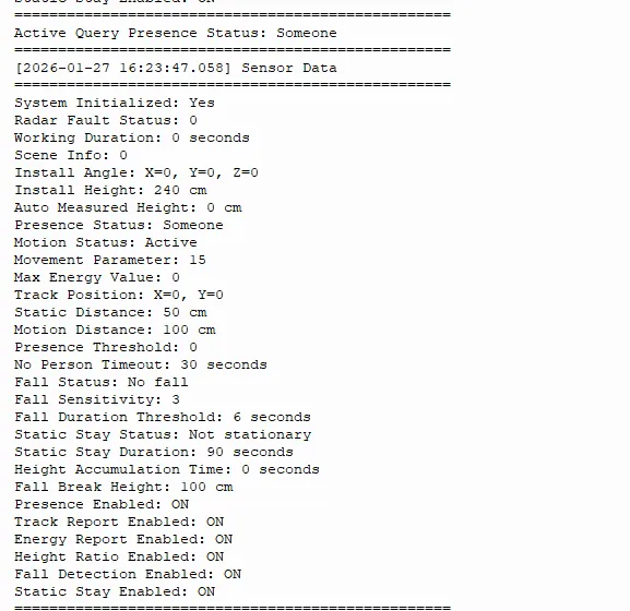
The same readout shows fall sensitivity 3, a 6-second duration threshold and a 100 cm fall-break-height setting. These describe the captured configuration. They are not recommended values for every room, and the readout does not measure the time from a real event to a notification.
A short duration chosen for a demonstration also needs separate thought from an eventual product's alert behavior. Ask what delay is acceptable, what ordinary activities could satisfy the condition, and what evidence would justify the selected setting. A setting acknowledgement only confirms that communication took place; read the value back and test its effect.
Make the software match the hardware before repeating the test
The carrier exposes a UART connection, with MTX and MRX named from the host's perspective. Our wiring table put the radar on GP8/GP9 and Bluetooth on GP16/GP17. The longer program we saved for the demo reversed those roles and imported an R60AMP1 trajectory-radar class instead of the R60AFD1 driver.
That program is therefore not a reproducible R60AFD1 example as saved. Before using a project like this as a build guide, reconcile the driver, wiring and baud rates against the actual board. Our photos and messages remain evidence of the demonstration, but they do not prove that the saved program produced it.
There are smaller version issues too. A trajectory-setting command returned a two-byte response where the manual we used describes four bytes, and it was unclear whether one acknowledged setting took effect. Firmware names also varied in our notes. Treat that as a reason to capture module identity and raw replies, not as a universal protocol correction.
For the next build, save a small known-working test that reads identity, configuration and status before adding Bluetooth presentation. Keeping that test separate makes it easier to tell whether a problem belongs to the radar, its parser or the phone connection. This is a proposed next step; we have not rerun the corrected setup.
Read the result at the level it supports
The phone showed Fall Status: 0 followed by Fall Status: 1, with presence still reported as 1, while a participant moved into low positions under the radar.
That supports a limited but useful statement: the prototype reported a fall-state transition during the demonstration. We have no synchronized footage, timed trial log, repeated outcomes or count of ordinary activities mistaken for falls. It cannot establish a detection rate or a missed-event rate.
In the next controlled evaluation, log what actually happened alongside the timestamped radar messages. Include ordinary sitting, bending, movement near the boundary and an empty room, as well as the intended test condition. Use a suitable supervised test procedure; do not ask vulnerable users to stage falls. Keep false alarms and missed events as separate outcomes rather than combining them into an unexplained "accuracy" number.
Test the enclosure as part of the room setup
The supplier guidance places clearances around the radar and between the antenna and a non-metal cover. A new enclosure is therefore another test condition. Check it in the intended orientation rather than assuming results from an exposed module carry over unchanged.
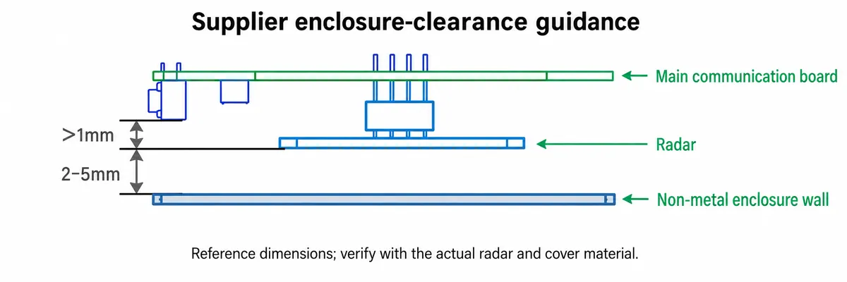
The next useful milestone is a documented room trial with a known board, matching firmware and driver, a measured mounting position, a saved configuration and a log of both expected and unexpected responses. That is a stronger basis for deciding whether to refine the enclosure, change placement or reconsider the sensor approach.
It is still a prototype evaluation, not a validated safety service. This build does not demonstrate dependable emergency notification or suitability as a sole safeguard. Before scoping the next round, write down the room layout, the intended event and the results so far; those details turn a broad detection idea into a specific integration and test task.