
You are building a device that measures a small change: pressure on a control, the output of a probe, or the weight of something on a platform. The first prototype produces numbers, but they move around. An external converter advertised as 18-bit or 24-bit looks like a straightforward upgrade. Before choosing one, decide how small a change the product must distinguish, and how quickly the user needs to see it.
Those requirements belong together. A slowly changing measurement can tolerate a wait that would feel wrong in an interactive control. More output digits also do not tell you whether the value is close to the real input. On our bench we ran two GraftSense ADC modules, an MCP3421 and a CS1237, on a GraftPort-RP2040 controller board under MicroPython. They show working acquisition steps, and what still has to be checked before promising accuracy.
Start with the change your user needs to notice
For a pressure control, a useful requirement might be "recognize a gentle press without jumping when nobody is touching it." For a measuring instrument, it might be "distinguish two nearby values after the reading has settled." Both teams might ask for a "high-resolution sensor," but they need different tests.
Write down the input range, the smallest meaningful change, the acceptable error and the acceptable response time. Resolution describes the available digital steps; accuracy is how far the result may be from the real input. Noise can make successive readings wander across several steps. Texas Instruments explains this distinction, including why extra bits alone do not settle the question.
The confusion is common. In a February 2026 All About Circuits discussion, a reader asks whether to use advertised resolution or effective performance when calculating an ADC's smallest step.
The 18-bit converter has more than one operating point
For the MCP3421 we fed a 1 Hz sine wave from a portable signal generator, set to a displayed amplitude of 1.6 V, into the module's SMA input. That gave a deliberately changing input to watch, rather than an unexplained sensor value. The generator's screen setting is not an independent measurement of the signal at the ADC.
This converter trades finer steps for fewer results. The Microchip MCP3421 datasheet lists these paired settings:
| Output resolution | Nominal conversions per second | What changes |
|---|---|---|
| 12 bits | 240 | More frequent results, larger steps |
| 14 bits | 60 | Intermediate |
| 16 bits | 15 | Finer steps, fewer results |
| 18 bits | 3.75 | Finest steps, longest conversion period |
These are converter settings, not accuracy grades. At 18 bits you get roughly one new conversion every 267 ms before software and display delays. That may suit a slow measurement; it is a different proposition from following a quick press.
Our recorded run reported 16 bits, a conversion time of 66,667 microseconds and gain 1, which matches the 15-per-second setting. One copy of our example program selected a raw rate value that the driver maps to 14 bits and 60 per second instead, so check which setting actually ran; the record is a 16-bit run, not an 18-bit one. Our wiring notes also named GP4/GP5 on the I2C0 connector, while the code created I2C1 on GP2/GP3. Make the physical connector and the program agree, and keep the working configuration with the result.
Keep the waveform, but ask what it establishes
The program first requested single conversions, waited for each conversion period and printed a voltage, then switched to continuous conversion while we plotted the result. The trace changed with the input, which shows the acquisition path responds. It is not a calibration: we had no synchronized reference trace, no measured generator offset and no error calculation across the range. Do not infer amplitude or timing accuracy from how the plot looks.
This is the point in a prototype review to add a few steady input points and compare the readings with a suitable reference instrument, keeping raw values and converter settings. Then go back to the moving signal and check whether the chosen rate follows the change your product needs to detect. We have not done those follow-up measurements yet.
The 24-bit example raises a different question: what turns counts into volts?
The CS1237 module has differential input terminals. Our program started at gain 1 and 10 samples per second, read five values, switched to 40 samples per second, and exercised buffered acquisition, temperature calibration and power management.
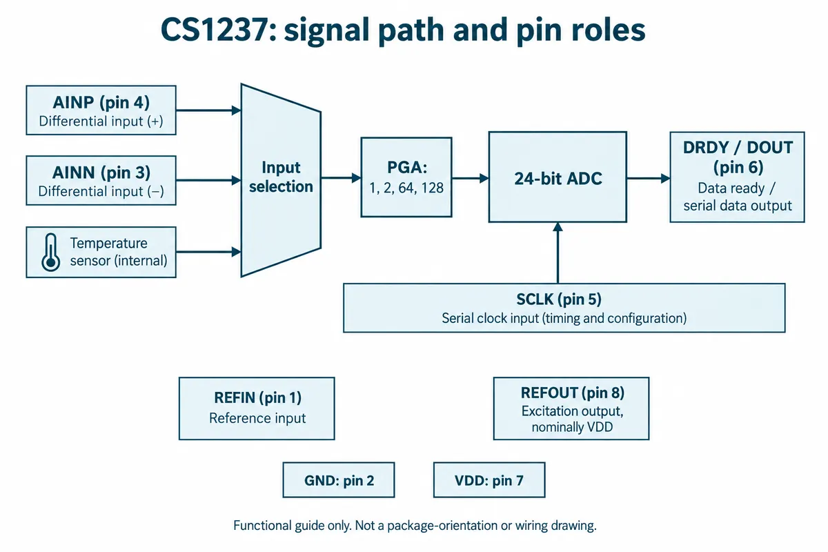
Although the board connector is labeled I2C0, this device uses its own SCLK and DRDY/DOUT sequence. Our program drove GP5 as the clock and used GP4 for data. A matching connector shape and an SDA/SCL label do not make the CS1237 an I2C device.
We applied 1.2 V to the positive input with the negative input grounded. The output showed raw counts around 7.67 million and displayed values near 1.143 V. The voltage came from the example's conversion: count divided by 8,388,607, multiplied by 1.25 V.
Before calling the gap from 1.2 V a measured error, establish why the formula uses 1.25 V. The CS1237 reference manual defines the ideal differential full-scale input as half the reference voltage divided by gain. The carrier schematic connects REFIN to REFOUT, which the manual describes as an excitation output at VDD. We did not measure the reference voltage, so nothing validates the fixed 1.25 V factor. "Correcting" every reading by a percentage based on this run would be premature.
For your own setup, record the reference arrangement, measure it where appropriate, and confirm gain and signed-data handling before converting counts into engineering units. The manufacturer's manual is the reference for the device; the carrier schematic tells you how a particular board uses it.
Let the measurement catch up with a configuration change
A product may change gain, wake from sleep or switch what it measures. The next displayed number must belong to the new state.
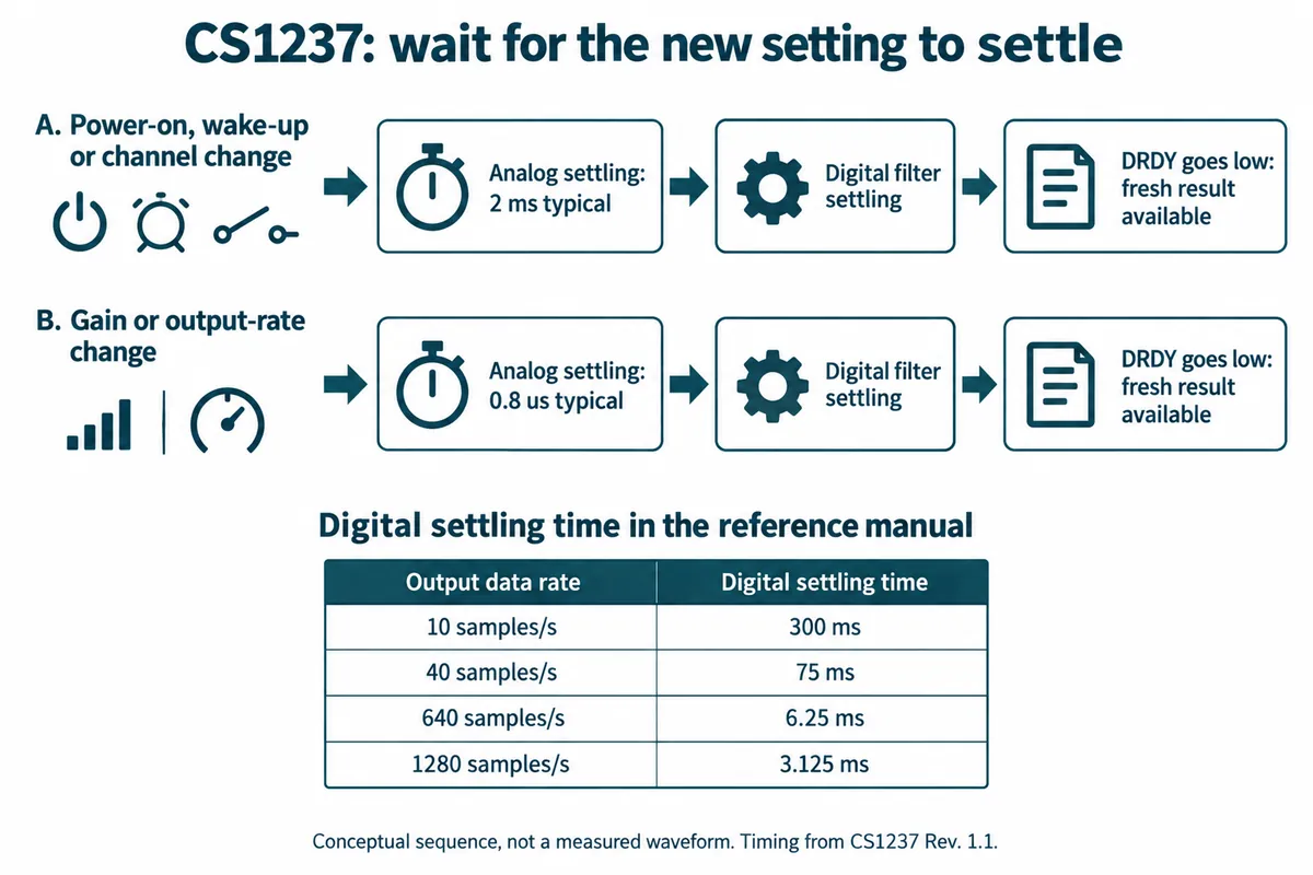
Our temperature routine also supplied 25 °C as the calibration reference before printing values close to 25 °C. That shows the routine runs; without an independently measured calibration temperature it says nothing about thermometer accuracy. Our log also ended at the wake-up message, with no reading after wake. Keep the power-management code, but get a post-wake reading before calling that part tested.
For a user-facing instrument, make "waiting for a fresh reading" a real state. Showing it briefly is better than presenting an old value as if it followed the latest press, setting change or wake-up.
Choose the next experiment before choosing the final converter
These two runs are starting points, not a contest between chips. The MCP3421 run shows how conversion rate and resolution move together. The CS1237 run shows why reference voltage, gain, communication and settling belong in the interpretation of a 24-bit result. Neither establishes the accuracy of a finished sensor product.
For the next build, keep a short test sheet with the input range, actual settings, raw counts, a reference reading and the time to a fresh result. Test the small changes that matter to the user, then repeat with the prototype's normal display, power supply and other electronics running. That tells you whether a module is enough or the surrounding circuit needs work.