
On a music controller, a physical knob makes an adjustment easy to find without watching a screen. A builder in an April 2020 MIDI-controller discussion wanted to grow a panel from 16 to 40 rotary encoders. Before attempting a bank of controls, a smaller experiment pays off: does one knob change the value in the expected direction, one deliberate movement at a time?
On our bench we connected a GraftSense EC11 rotary encoder module to a GraftPort-Pico controller running MicroPython and showed its count as a progress bar in the terminal. That simple setup is enough for a team considering a physical level, menu or selection control to compare the hand movement with the reported value before building the finished interface.
A turning input does not report an angle
This is an incremental encoder. Its two channels, A and B, change in a sequence as the shaft turns, and the firmware uses the order of those changes to decide direction and count movement. Unlike a potentiometer with fixed endpoints, where the knob points says nothing about the selected value.
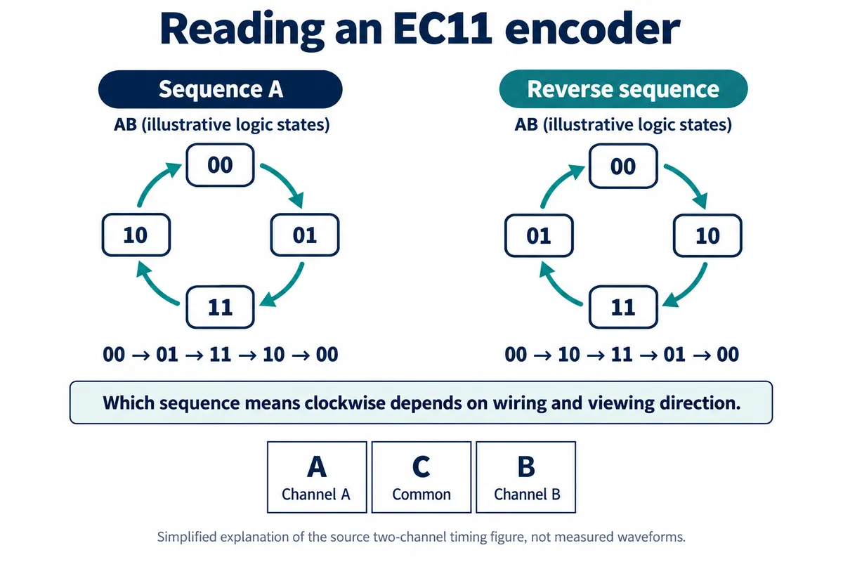
Read the order of the two channels. A shorthand like "both edges arrive together" is not a substitute for that phase sequence when you implement direction detection.
A 2018 Arduino forum question raised the presentation side of the same fact: an arrow on the knob implies a position that means nothing to an encoder-based interface. Decide whether the value will appear on a screen, a light ring or another indicator before you choose the knob's markings.
Connect the two channels the module actually exposes
The module's connector carries GND, VCC and two channel signals. We connected them through the controller's DIO0 connector, channel A to GPIO6 and channel B to GPIO7. One comment in our example code named different GPIOs from the ones the program actually used; trust the pin assignment in the constructor and the connection table, not the comment.
The component has separate push-switch terminals, but this module does not route them to its connector. That matters if your concept is "turn to select, press to confirm." Our connection supports the turning action; it does not provide the press. Plan a separate input, or a board that actually exposes the switch signal, before promising press-to-confirm.
Use the count display to test the basic feel
The test program used our team's EC11 driver package, read the rotation count every 10 ms, printed it, and drew a terminal progress bar scaled to a maximum of 20. Our example also had a branch meant to reset the count with the encoder's button; with the switch not wired out, that branch has nothing to read and needs rework.
The terminal recording shows the count changing as the knob turns, and the progress bar following it. It does not measure missed transitions, contact bounce, or how each detent maps to a software increment. Those are the next checks before the value controls a product function.
Try the movements a person will actually make
Turn slowly in one direction, reverse near a detent, then turn quickly. Compare the result with the intended meaning of one step. A 2023 Arduino discussion describes readings that looked fine at low speed but reversed direction unexpectedly when turned fast. That is someone else's reported problem, not a measured failure of this module, but it is exactly the case to test.
Our driver uses software debounce. Debounce deals with short, unwanted contact transitions, but how often the application reads the count and how long the display update takes matter too. Keep the raw count visible while tuning the user-facing scale, so a skipped input is not confused with a slow display.
Once the basic input is consistent, decide the product behavior: minimum and maximum values, whether faster turns should move further through the range, and what the value should be after power is restored. A terminal bar reaching 100% decides none of these for you.
Finally, check the populated part. Manufacturer family tables for EC11 encoders cover many variants; confirm the exact part on your board before relying on its endurance or dimensional figures, and before designing the panel cutout and knob around it.