
A prototype data logger can look busy for the wrong reasons. You press Export, the program starts sending readings to a computer, and the buttons stop responding. Moving the transfer into the background can help, but it raises another question: when should the screen say the export is finished?
That question matters before a development-board demo becomes something another person uses. Returning from a function, handing the last byte to a hardware buffer, and the computer receiving a complete record are different events. If the software treats them as one, a reassuring "Done" can appear too early.
We looked at this on an RP2040 board running MicroPython 1.23.0 with three DMA experiments: copying a block of memory, sending a generated waveform over a serial link, and assembling several pieces of text with two chained DMA channels.
Give the processor another job, not a faster cable
DMA stands for direct memory access. Software gives a hardware controller a source, a destination and a transfer count, and the controller moves the data without the processor copying each item. A sensor instrument could use that time to handle a button or update its display.
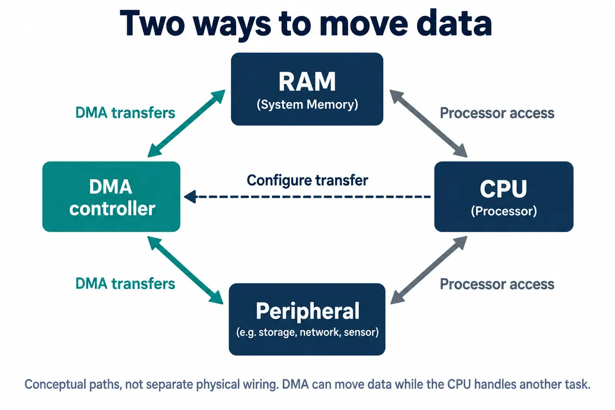
The receiving peripheral still sets the pace. A serial port does not send bytes faster because DMA supplies them. Think of DMA as keeping the outgoing tray stocked while the processor does something else; the tray and the cable still take time to empty.
Experiment 1: a memory copy
The first test left the serial port out. It filled a source array with the integers 0 through 1023 and prepared a destination array of the same length. The transfer used four-byte words, so a count of 1024 meant 4096 bytes. The timing code looked like this:
start_time = time.ticks_us()
dma.active(1)
while dma.count > 0:
    pass
end_time = time.ticks_us()
The empty loop is the important part: this version waits for the copy instead of doing anything useful in the meantime. The run reported 104 microseconds for the DMA path and 314 microseconds for a Python slice copy, and both arrays showed the expected sequence. Those are results for those code paths in one run. The slice also creates a new object, and the DMA path spends its time polling, so the comparison does not show an application doing useful work concurrently or a general speed multiplier.
For a prototype, the first check is simpler: does the destination hold the intended data? Only after that does it make sense to measure how much processor time the transfer frees. A fast copy that occasionally damages a record is not an improvement.
Experiment 2: send a known pattern before real measurements
The second test added a serial link and a computer running SerialPlot. Instead of noisy sensor readings, the program generated 1000 unsigned byte values following one cycle of a sine wave. A known pattern makes a missing section or a wrong interpretation easy to spot.
The UART ran at 115200 baud, 8 data bits, no parity, one stop bit. SerialPlot was set to simple binary, one channel, unsigned 8-bit values. Choosing text or a different sample width would change what the same bytes mean.
The DMA writer feeds bytes from the source buffer into the UART data register. The source address advances; the destination stays fixed. A hardware request from the UART paces the transfer so DMA supplies data only when the peripheral can take it. That is why a memory-to-memory setup cannot simply be pointed at a serial register without changing its configuration.
Our notes on this setup had an unresolved inconsistency: the code used RP2040 register addresses, while a wiring table listed different pins from the ones in the code. Confirm the actual board, firmware, pin assignment and adapter voltage before reproducing it.
The program then ran a blocking DMA call, a non-blocking DMA call and an ordinary UART write. Blocking means the function waits before returning; non-blocking means it can return while the transfer continues. The console reported 52 microseconds for the non-blocking DMA call and 63,543 microseconds for the ordinary write.
The 52 microseconds is not the time for 1000 bytes to travel down the cable. In that implementation, DMA starts before the first timestamp is taken, and the non-blocking path does not wait for completion. At 115200 baud with 8N1 framing, each byte takes ten bits on the wire, so 1000 bytes need at least 86.8 milliseconds of continuous transmission. That is a calculation from the configured format, not a measurement. Neither function duration proves that the receiver has the full block.
The receiving side is better evidence. SerialPlot showed the expected waveform, and we exported it to a CSV file with 1000 samples. Compared offline with the sine formula, 999 values matched; the midpoint differed by one count from a desktop double-precision calculation. Floating-point rounding is a possible explanation, but the record does not establish the cause. We would not call this a verified byte-for-byte match without capturing and comparing the actual transmitted buffer.
Decide what "finished" means in your product
For a background export, define the completion event before writing the success message. There are at least three checkpoints:
- DMA has finished reading the source buffer. DMA no longer needs those bytes. It does not mean the UART has shifted the final byte onto the wire.
- The UART transmitter is idle. The local transmitter has finished sending. It does not mean the receiving application accepted the complete record.
- The receiver validates and acknowledges the record. The agreed receiving check passed. It does not mean the data was durably saved unless the protocol confirms that too.
The distinction shows up in real troubleshooting. In an ST community thread from October 2023, a developer asked why normal-mode transmission needed a separate UART completion interrupt. It is a different MCU and software stack, but the same question.
Our DMA writer also had a callback argument that needs care. It calls that function directly after its optional waiting loop, so on the non-blocking path the callback is not a hardware completion notification. Naming a function "complete" does not make it wait for the hardware. The MicroPython rp2 DMA API has a separate interrupt interface; check the firmware version and interrupt configuration when you implement it.
For ordinary UART use, the MicroPython UART documentation describes flush() and txdone() for waiting on or querying transmit completion on supported ports, including rp2. With a custom DMA writer, first establish that DMA has finished supplying the peripheral, then check the transmitter. An idle check made before DMA has supplied its first byte gives the wrong answer. We have not yet tested those calls in this setup.
A practical export test would add a record number and length to each block, have the receiver check the payload, and press buttons or update the display while data moves. Keep the source buffer alive and unchanged until DMA has finished reading it. Decide what happens if the receiver disappears or the operation times out.
Experiment 3: assembling a record from several pieces
The last test joined six pieces of text into a 64-byte destination buffer. One DMA channel reads length-and-address pairs and writes them into the control registers of a second channel, which copies the corresponding bytes. When a fragment is done, the second channel triggers the first to fetch the next pair.
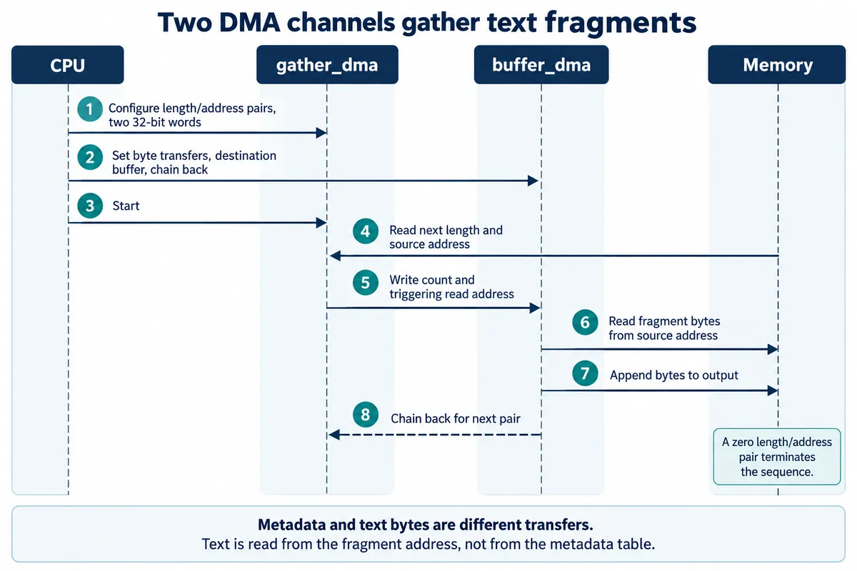
The output buffer began with the joined 46-byte ASCII test message, followed by unused zero-filled space. That demonstrates gathering a small set of ASCII fragments. It does not demonstrate arbitrary text encodings, continuous sensor logging or a production packet queue.
For a product, this could avoid building an extra combined copy of a header and several data fragments. It also makes ownership harder to follow: every referenced fragment must stay valid until its transfer finishes. The control pairs use two four-byte words each, while the text moves in single bytes. Mixing up those counts is an easy way to copy the wrong amount of data.
Start with an ordinary buffered write if it already meets the prototype's needs. Consider DMA when measurements show that moving data interferes with another required task. Then compare complete, correct transfers under the intended workload, including the time spent preparing buffers and handling completion.