
Your project may not need a new sensor. A scale, a lab instrument or an installed audio system may already do the hard job and expose a serial port. The new prototype could add a simpler control panel, collect readings, or connect that equipment to the rest of your workflow.
The challenge is that "it has RS-232" does not mean "any serial cable and a few lines of code will work." Electrical levels, cable wiring, communication settings and device commands all have to agree. Testing them separately makes the integration much easier to understand.
On our bench we used a GraftSense MAX3232 module to let a GraftPort-RP2040 board exchange text with a computer through a USB-to-RS-232 adapter. That proves the communication path. The target instrument's command protocol is a later test.
The adapter solves the electrical part
A microcontroller's UART pins use logic-level signals. RS-232 uses a different electrical representation, including positive and negative voltages. Do not connect an instrument's RS-232 transmit pin directly to an RP2040 GPIO.
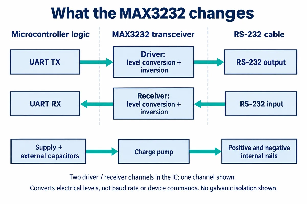
A MAX3232-type transceiver sits between the two. Its drivers and receivers translate and invert the signals, and a charge pump with external capacitors generates the internal rails it needs. It does not turn a scale command into an audio command, change the baud rate or decide when a response is complete.
Our module uses one transmit/receive channel of a UMW MAX3232. The chip's package pin names are not the same as the labels on the module's four-wire host connector, so do not confuse the two.
The module circuit has a regulator and a shared ground, with no galvanic isolation. Treat it as a bench interface until the final installation's grounding, cable exposure and protection needs have been reviewed. A successful exchange on a desk is not an industrial immunity test.
A connector that fits may still need a different cable
Nine-pin D-sub connectors are often called DB9 in serial documentation. Their appearance does not tell you which device transmits on which pin.
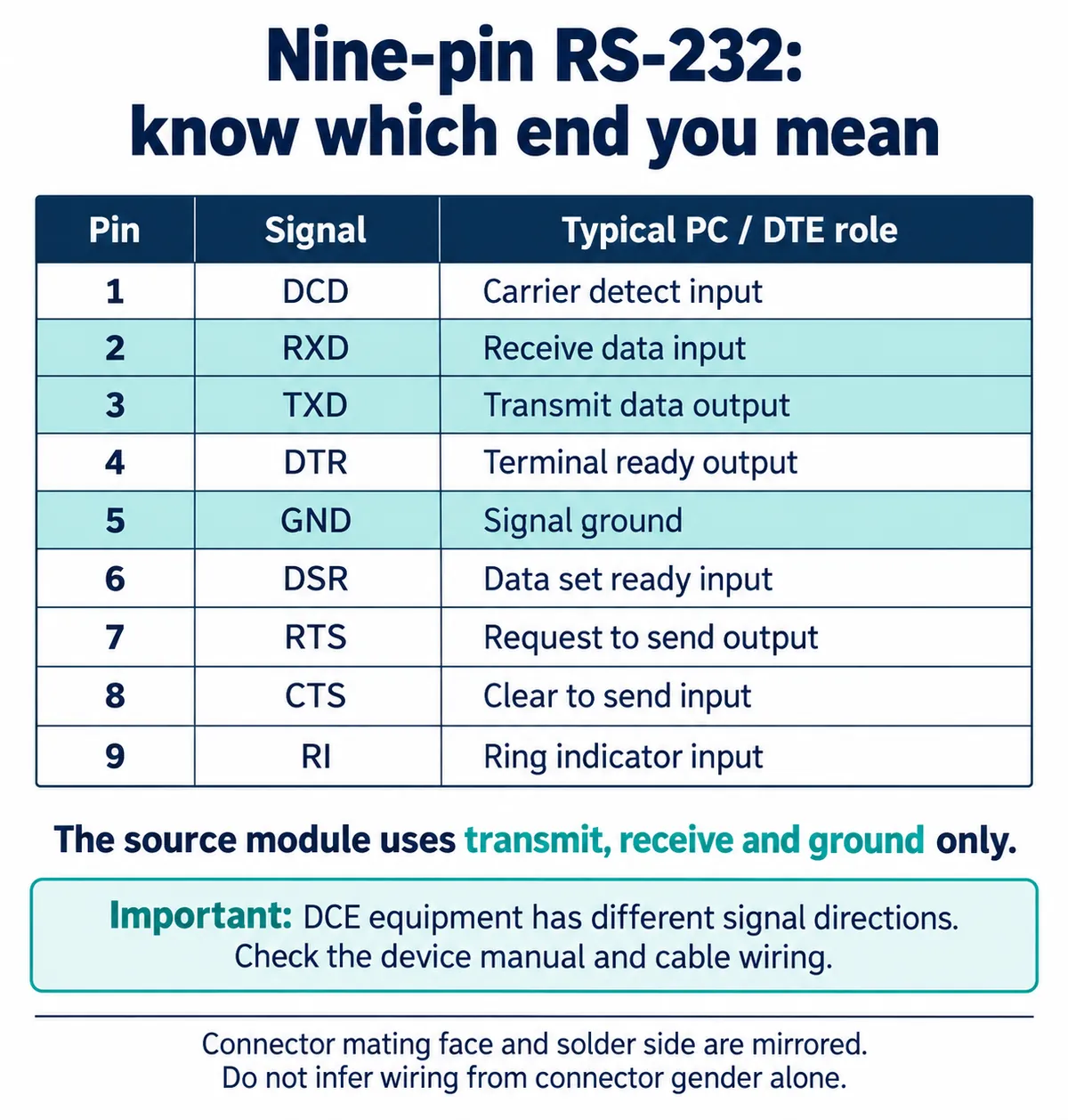
Our module sends data on connector pin 2, receives on pin 3 and uses pin 5 for signal ground. That is the reverse of the conventional PC/DTE transmit and receive directions. Match the two endpoints and trace the cable, rather than following an unconditional "always cross TX and RX" rule.
An Arduino instrument-control thread from April 2015 shows exactly this trap. A signal generator worked from a PC but not from the microcontroller setup, and the author reported solving it with a different cable arrangement for the second endpoint. That fix applies to that setup; the lesson is to verify both ends of yours.
Only transmit, receive and ground are used by this module. An instrument that requires hardware flow control needs those signals handled separately. TI's full modem-interface reference design shows the difference between a data-only connection and one with additional control signals; a three-wire test does not exercise them.
Bring up the computer side before adding the instrument
We used a USB-to-RS-232 adapter, not a USB-to-logic-UART cable; those are different electrical interfaces. Ours needed a driver for its own chipset on Windows. Use the driver for your actual adapter, from the vendor's current instructions; a USB plug does not identify the chip inside.
Once the port was available, we set the terminal to 9600 baud, eight data bits, no parity and one stop bit. Select whatever COM port your computer assigns to the adapter; a port number in someone else's screenshot is not a setting to copy.
On the GraftPort-RP2040 side, UART1 uses GP8 to transmit and GP9 to receive, and the module's MTX and MRX labels describe those microcontroller roles. Follow that connector mapping and the circuit rather than guessing direction from similarly named internal nets.
Send a known message and watch both directions
Our test program sent a numbered text message, waited briefly, read whatever had arrived and paused before repeating. This version makes the serial format explicit and prints raw bytes rather than assuming every reply is UTF-8 text. It is for a terminal test like ours, not an instrument command; we have syntax-checked it but not rerun it.
from machine import UART, Pin
import time

uart = UART(1, baudrate=9600, bits=8, parity=None, stop=1,
            tx=Pin(8), rx=Pin(9))
count = 1
while True:
    message = "Test message %d: Hello, UART loopback!" % count
    uart.write(message.encode("utf-8"))
    time.sleep(0.1)
    received = uart.read()
    print("Received bytes:", received)
    count += 1
    time.sleep(2)
Look closely at what happened. The PC terminal received the numbered messages. The microcontroller reported no data on most passes, but did receive test and later a grouped testtesttest typed on the computer. That supports a two-way exchange. It does not show an automatic echo of every message, even though the program called itself a loopback test.
The grouped reply is useful evidence too: a read call is not a message boundary. According to the MicroPython 1.23 UART documentation, reads return whatever bytes are available or stop at a timeout. Your device protocol has to tell the application how to recognize a complete response.
Now ask the real device one documented question
Once the terminal path works, collect the target device's interface manual and a known-good exchange. Record its baud rate, data format, flow-control requirements and command terminator. Some devices stream readings; others wait for a request or a front-panel action.
This is partly a device-setup issue, not only a programming one. Many instruments need their serial output enabled or assigned a role in their own menus; Biamp's Tesira documentation, for example, shows that a serial port can be configured for different control roles. Do not assume one product's settings apply to another.
Start with one documented, non-destructive query. Compare the raw bytes the prototype receives with the working PC exchange before adding a display or a database. Then test a delayed reply, a disconnected cable and a device restart. The interface should tell "no new reading" apart from a real zero or a successful command.
At that point you have a useful integration milestone: one meaningful operation works with the actual equipment, and failures are visible. The exact device model, its interface manual and a sample exchange captured from a PC are the three things that make the rest of the controller or data-collection work concrete.