
Your temperature monitor already works. Now you want to build a few more, and a different sensor is described as DS18B20-compatible. Keeping the connector and most of the software sounds appealing. Before making the change, check three things together: the module's wiring, the driver's interpretation of its readings, and how long the program waits for a measurement.
On our bench we connected one GraftSense MY18E20 temperature module to a GraftPort RP2040 carrier with a Raspberry Pi Pico and printed temperatures through MicroPython. This note covers what that first reading established, and what you would still need to check before swapping a sensor across several prototypes.
The question is an old one. In a January 2020 Arduino forum discussion, someone tried reusing an older DS18S20 probe with a DS18B20-based thermometer and reported an implausible fixed reading. Those are different parts from the MY18E20, but the underlying question is the same: does a similar interface mean the existing instrument will understand the replacement?
Start with the module you will actually connect
Our test used a bare sensor module and a four-wire cable. It is not a sealed probe, and it says nothing about waterproofing or measurement inside a finished enclosure. That matters if your product is a plant monitor, an equipment logger or any device where the sensor sits away from the electronics.
The chip and the module have different power arrangements. The MY18E20 manufacturer sheet gives a chip supply range of 1.8 to 5.5 V. The module schematic, however, labels the connector supply as +5 V and shows an XC6206 regulator providing +3.3 V to the sensor, with a 4.7 kΩ pull-up on the data line to that 3.3 V rail. A chip's allowable voltage does not tell you which voltage belongs on every connector pin.
The module connected to the carrier's DIO0 port: GP6 carried the data signal and GP7 was unused. GP6 means GPIO 6, not physical header pin 6. On another carrier, trace the connector's ground, supply and data positions before connecting; cable colors are not a pinout. The chip itself has three connections: ground, DQ for data, and VDD for power. That package pinout is not the four-position module connector.
A one-wire interface still needs the right electrical setup
"One wire" describes the data connection. An externally powered setup also needs power and a shared ground. On DQ, either side can pull the line low, and a pull-up resistor brings it high when both release it. That is why the pull-up voltage and the controller's input limits belong in the same wiring check.
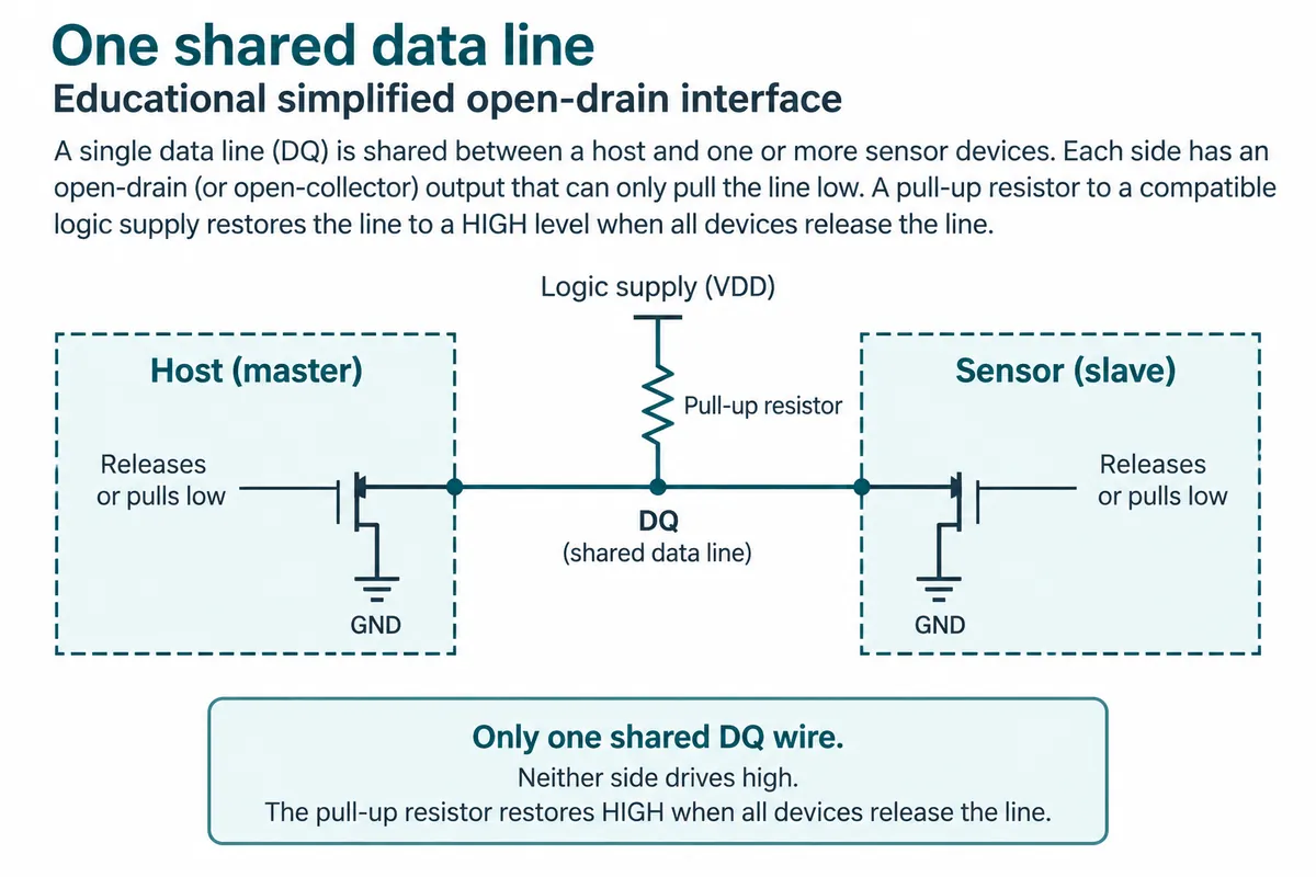
The manufacturer's typical circuit is useful background, but it is not the module circuit we used. It shows a 10 kΩ pull-up where the module uses 4.7 kΩ. Do not add a pull-up to a different supply because it appears in a generic example, and do not read the chip's 5.5 V limit as permission to put 5 V on an RP2040 data pin.
For a first replacement test, keep the carrier, cable and power arrangement unchanged wherever possible. Then a changed result points at the sensor rather than at something else that changed at the same time. Longer cables and multiple probes are separate tests; a one-module bench setup does not validate them.
Reproduce the software path
We used MicroPython 1.23.0 and our team's MY18E20 driver package, version 1.0.0, which includes a OneWire layer, the sensor driver and an example program. If you use a driver from any source, keep the exact package version and its license with your test record.
The example waits three seconds at startup, creates a OneWire connection on GP6, scans for sensor addresses and requests a conversion. It then waits, reads each discovered sensor, prints the result and requests another conversion. Our run found one address, so it demonstrated one connected sensor even though the program can iterate over a list.
Inside the sensor, a conversion produces a digital value that the driver retrieves from the scratchpad, a small group of working registers. Receiving those bytes is only part of the job. The driver must check them and convert their bit pattern into a temperature for the selected operating mode.
Keep the wait time with the part number
The example waits 500 milliseconds between requesting a conversion and reading it. A nearby code comment says 750 milliseconds, so the comment gives a misleading account of the run. The MY18E20 sheet (revision 202411-V3.9) lists a 500 ms maximum conversion time for the standard device; a faster variant of the part should not be assumed.
For comparison, the DS18B20 data sheet, page 3, specifies up to 750 ms at 12-bit resolution. A 500 ms wait copied from our test is not a universal setting for a DS18B20 replacement. Check the actual device and resolution, then allow its specified conversion time or use a correctly implemented completion check.
Resolution is also different from accuracy. At the ordinary 12-bit setting, a 0.0625 degree C step shows how finely values are represented, not how accurate the measurement is. The driver exposes 9 to 12-bit settings. The manufacturer's additional 14-bit claims were not part of our test.
Read the result, and make a failed reading visible
The console showed repeated readings around 26.75 degrees C, ranging from 26.625 to 26.875 degrees C. That establishes that this assembly and program produced temperature output during the run. There was no reference thermometer, so those decimals are not a calibration result.
The driver checks the scratchpad's CRC, a checksum used to detect corrupted data, and its read method returns None when that check fails. An application that only catches exceptions can miss this failure path; it also has to check whether a temperature was actually returned.
For a display or logger, decide how a failed reading should appear before a user meets it. For example, show "reading unavailable" and keep the time of the last valid sample. Do not label an old value as a fresh measurement. We propose that behavior; our bench run did not test it.
What would make the replacement convincing?
Treat the successful bench reading as the start of a comparison. Record the exact module and firmware versions, then run the replacement beside the current sensor under the conditions your prototype will meet. Compare both with a suitable reference if the decision depends on accuracy. Check startup, disconnection and reconnection, and repeat with the intended cable and enclosure.
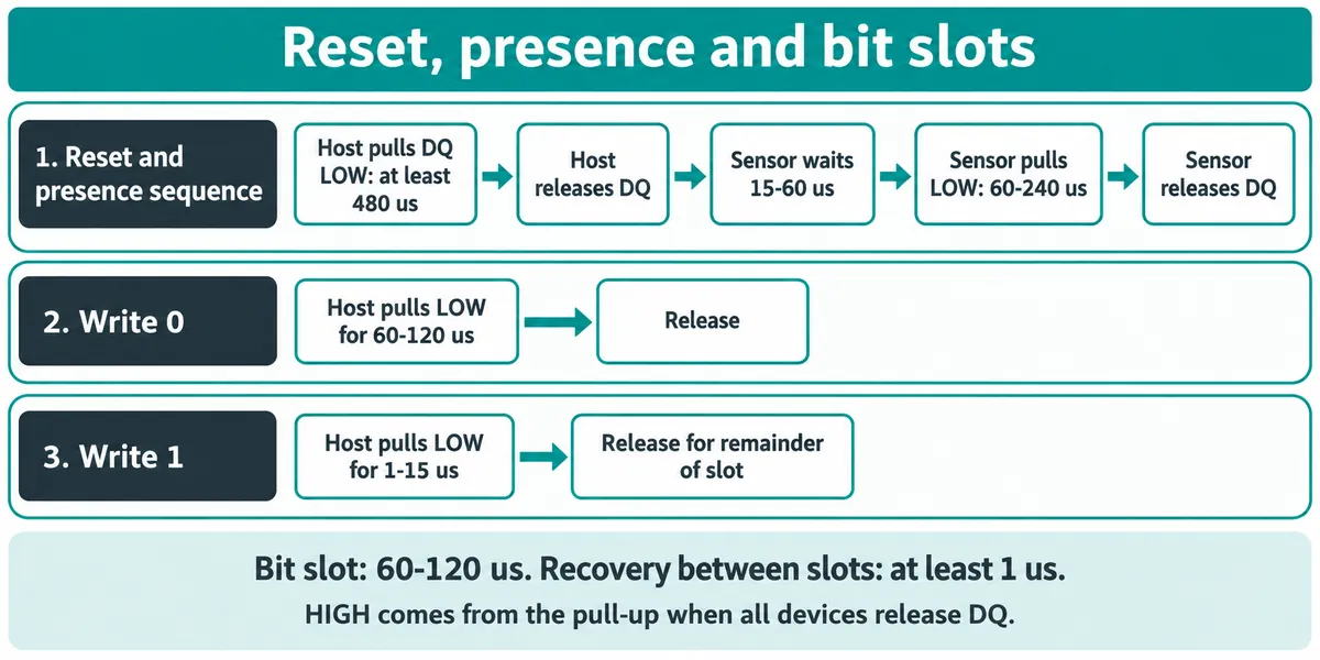
For whoever writes or reviews the driver, the microsecond-scale bus operations are separate from the much longer conversion wait:
A replacement decision should end with a bounded statement: this module, driver, wiring and operating mode worked under these recorded conditions. Our test supports a one-module reading experiment. It does not establish interchangeability across every advertised mode, long cable, host controller or production unit.