
Your prototype works on the desk. Now you want to put it in a portable case and let someone use it for a day. How large does the battery need to be? Before comparing capacities, you need a trustworthy picture of what the complete device draws while it waits, wakes up and does its job.
A current-monitoring board can turn that question into a bench experiment. On our bench we used a GraftSense INA226 module, a GraftPort-RP2040 controller, an adjustable supply and an electronic load. This note covers the wiring, the software settings, and one result that told us to stop and check before trusting the numbers for a battery-life estimate.
Decide what belongs inside the measurement
If you measure only the sensor, you miss the controller, the power conversion and the display. If you measure a development board, its indicator LEDs and support circuitry may draw power that your later custom board will not. Neither measurement is wrong; they answer different questions.
Start by drawing a boundary around the assembly your battery will supply. Include the regulator and peripherals if you want a whole-device estimate. Then list the states a user will see: waiting, sensing, showing a result, transmitting or moving. You will need both the current in each state and the time spent there.
The monitor measures a small voltage in the power path
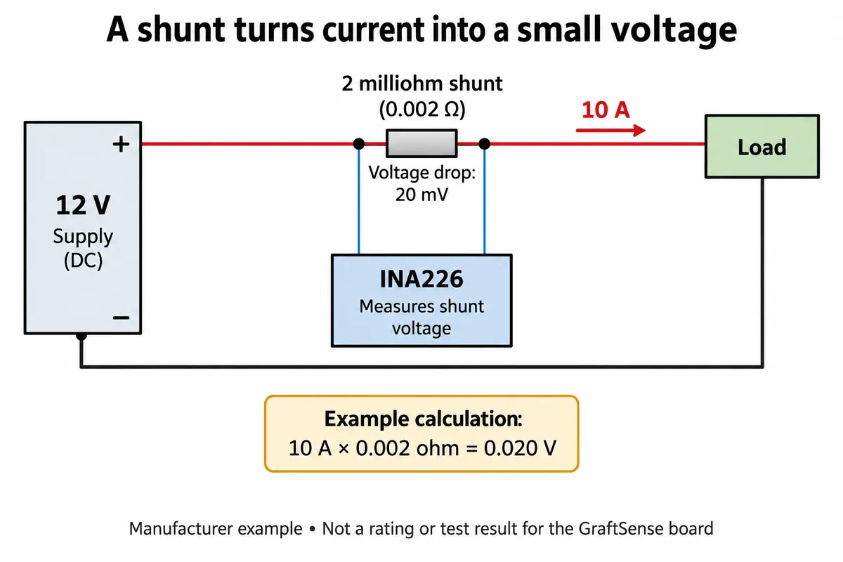
The INA226 measures the voltage drop across a low-value resistor, the shunt, that the load current passes through. Knowing the shunt resistance turns that drop into current; the bus voltage is the second input needed to calculate power. The controller reads the results over I2C.
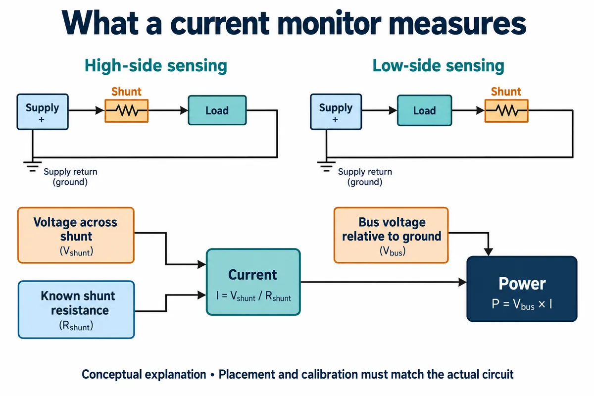
Keep the two connections separate in your head. The load current flows through the shunt terminals. The I2C connector carries control-side power and data; the load is never powered through SDA or SCL. Also, the chip's allowed measured-bus voltage says nothing about the supply voltage for the module's logic connector.
The board marks its load-path terminals VIN+ and VIN−, with ground terminals between them. VIN− is the downstream side of the shunt in the positive supply path, not another name for supply ground. Read the actual board markings when you connect it, and on the address pads select one intended option per address input rather than shorting options together.
Wire a simple, known load first
We connected the module to the controller's I2C0 connector, with GPIO 4 as SDA and GPIO 5 as SCL. A separate adjustable supply and an electronic load created the current being measured. An electronic load is a test instrument that draws a set current, so it can stand in for a product while you check the measurement chain.
With power off, put the monitor in series: supply positive to IN+, IN− to the load's positive input, and the load return to supply negative. The monitor and controller need the intended common ground reference. Instruments label their input and return differently; follow the instrument's documentation rather than matching words.
Start with a modest, known load inside the limits of the fitted shunt, connectors and wires. The module schematic shows a regulator from a +5V net to the INA226's 3.3 V supply, so check the module's own supply requirement; the chip's supply range alone does not tell you how the board behaves when powered through its connector.
The shunt also changes the circuit slightly: it drops voltage and dissipates heat. TI's worked example shows the relationship.
Make the software agree with the hardware
We installed version 1.0.0 of our team's INA226 driver package, which builds on an ina_ti module and a small I2C adapter dependency. Keep the driver and its dependencies at matching versions when you reproduce a setup like this. Before anything else, confirm the bus:
from machine import Pin, SoftI2C

i2c_bus = SoftI2C(sda=Pin(4), scl=Pin(5), freq=100000)
print([hex(address) for address in i2c_bus.scan()])
The example program then created the sensor at address 0x40 with a shunt resistance of 0.01 ohm (10 milliohms) and a maximum expected current of 2 A. Those two values set how the driver scales readings. They are not a current limit. The module schematic shows two 10-milliohm resistor positions, R1 and R2, in parallel. If both are fitted, the combined resistance is 5 milliohms, and a 0.01 setting would be wrong by a factor of two. Check what is actually populated before you copy any software value.
The program took ten manually triggered readings, then switched to continuous measurement, printing shunt voltage, bus voltage, current and power. That is a sensible way to confirm communication before building a logger. For a single triggered conversion, poll the conversion-ready flag with a timeout instead of assuming a fixed delay covers the whole measurement: a combined shunt-and-bus reading needs both conversions plus any averaging. Also check the math-overflow flag. A ready flag only means new data exists; it does not prove the wiring, resistance value or range is right. TI's INA226 datasheet describes the calibration and conversion behavior behind these checks.
The result we did not accept
The terminal showed successful initialization at 0x40, then manual and continuous output. Bus voltage varied around 4.76 V and the reported current stayed close to 2 A, which looked like the constant-current setting on the load. The shunt reading gave a reason to pause: it sat at exactly 0.0819175 V in every line.
That is 32,767 counts at the INA226's 2.5 µV shunt-voltage step, the highest positive signed reading. It is a full-scale warning sign, not a stable measurement. With a 0.01 ohm setting, 2 A should produce about 0.020 V across the shunt. The recorded values do not agree with that relationship, and the log alone cannot tell us whether the cause is wiring, configuration, the driver or something else.
The electronic load's own display in a separate photo of the same bench read about 3.819 V and 1.998 A, while the terminal showed around 4.76 V. Those were different recorded conditions, not a synchronized comparison, so they prove nothing about accuracy. The wiring and code are a useful starting point; the current and power values need a fresh check.
For that check, start at zero load, then step through several known loads. Compare the monitor with a reference meter under the same condition, measure the voltage across the actual shunt, and confirm that reported current changes in proportion. Check overflow and range limits. Save the board population, software version and readings together so someone else can repeat the comparison. If you lay out your own board, use separate Kelvin sense connections at the shunt, as in TI's layout example, so drops along load-carrying traces stay out of the measurement.
Turn trustworthy readings into a power budget
Once the measurement behaves, replace the electronic load with the prototype and exercise its real features. Watch a wireless device while it waits, wakes and communicates. Run a motorized object through its intended movement and load. Set a display to the brightness and update rate planned for the user trial.
An Arduino forum discussion from February 2020 describes the same problem from a product developer's side: intermittent LED and electromagnet activity made a single current reading useless for choosing batteries, and the author ended up tracking activity duration alongside measurements.
For reasonably steady states on the same rail, charge use is current in milliamps times hours, summed across states and multiplied by how often the user repeats each action. If you measure after a voltage converter, account for conversion losses before translating to battery demand, and compare energy rather than treating milliamp-hours at different voltages as interchangeable.
Our continuous loop printed every 500 ms. That is fine for watching steady values but will miss short startup or radio bursts and very small sleep currents; those need a measurement method chosen and verified for them. A smooth serial log does not prove the supply never dipped.
The useful deliverable at this stage is a record of operating states, measured consumption, timing, supply conditions and uncertainties, not a runtime promise based on one log. Then test the chosen battery and the assembled prototype together before a user trial.