
Your prototype can measure light, but the person trying it still needs a laptop to see the result. For an interactive display, a classroom device or a simple environmental indicator, the next useful step is to make that reading visible on the object itself. You can then check whether people understand the response before committing to a custom board or enclosure.
On our bench we built a small light-feedback prototype: a BH1750 light sensor drives an eight-segment LED bar, with a GraftPort-Pico controller and a battery power module, all inside a clear acrylic enclosure. This note covers how the measurement becomes a readable signal, and what remains to decide for a particular product.
Start with one response that people can see
The prototype lights more segments for higher light readings. It uses a demonstration range of 0 to 2000 lux, mapped to eight display levels. Lux describes illuminance at the sensor; the bar gives the user a quick visual comparison without asking them to interpret a number.
For a classroom light indicator, that scale gives people something they can change and observe. It is a design choice, not a universal definition of a well-lit desk, a healthy plant or a safe workspace. Before changing the hardware, decide what you want someone to infer from the bar: simply "brighter than before," or something that should lead to an action. The second promise needs evidence from the intended environment.
The build has three functional modules: a PCF8574-based LED-bar module, a BH1750 light-sensor module and an SY7656 battery-power module. They do three separate jobs: show a level, measure light and supply power. Keeping those roles visible makes the first prototype easier to troubleshoot.
Build a chain you can check one connection at a time
The BH1750 connects to the controller's I2C0 connector and the LED bar to I2C1. The sensor starts at address 0x23 and the bar's PCF8574 controller at 0x20; the program scans for devices during initialization.
If the bar stays dark, first establish which part of that chain is missing. A bus scan tells you whether a module answers at all. A responding sensor with a silent display is a different problem from a system where neither module appears. Check connections, power and addresses before changing the display logic.
The battery connects to the power module's BAT socket, and the module's output supplies the main board. One two-pin lead in our build had an unusual color assignment: red was ground and black was the supply. Match connector markings and measured polarity rather than assuming a red wire is positive.
Assemble early enough to expose practical questions
The boards sit on M3 plastic standoffs, with clear panels screwed around them. Assembling early shows where the sensor, display, power switch and charging connector sit relative to the enclosure, and whether each is still reachable.
Keep the power and reset controls accessible. On the controller board revision we used, one position of the RUN switch has to be set to conduct when no external watchdog module is fitted. Check the equivalent setting on your own board revision.
The firmware structure
The firmware runs on board-specific MicroPython v1.23.0. Initialization lives in main.py, pin assignments in board.py, settings in conf.py, and the sensor-to-display work in a task file that reads the sensor, maps the result and updates the bar. The configuration retries I2C initialization up to three times with a half-second delay, keeps debug output on during setup and starts the task automatically. The controller's onboard button pauses and resumes updates.
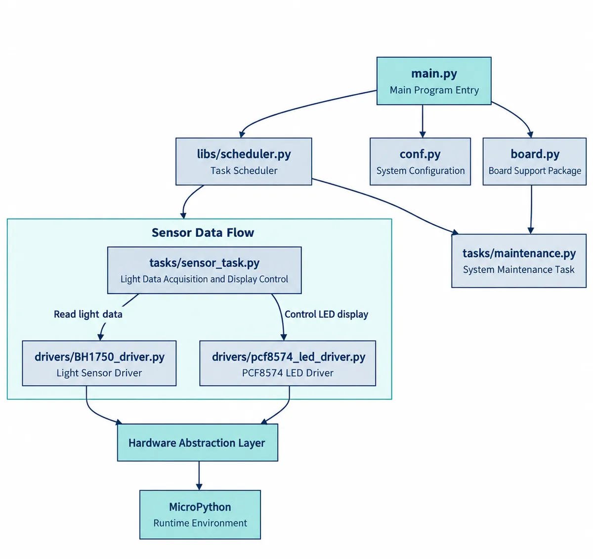
That separation is useful when the product question changes: you can try a different mapping from lux to segments without rewriting the communication code.
Our functional test was simple: cover the sensor or direct light toward it, and watch the bar respond. Repeat that action before judging a more elaborate interface. Also try the pause button: a frozen display needs to make sense to someone other than the developer.
Decide what the enclosure changes
A reader in an Arduino discussion from September 2022 asked how to cover a BH1750. That remains the relevant question for this build: the sensor's mounting and optical cover are part of the measurement path. A finished-looking box does not settle what the readings mean.
For the next version, compare the same light conditions with the intended cover fitted and removed, keep the sensor position consistent, and write down what each display level should communicate. Our bench test showed changing feedback. It did not produce a calibrated reading through an enclosure or a user study; those are the next steps before someone else relies on the bar.