
Your prototype has finished a task. The code knows it, but the person using it may be looking away, wearing headphones or holding the device in a noisy room. Before adding a louder buzzer or a brighter light, decide what that person needs to notice, and what they should do next.
On our bench we ran three small output experiments on a GraftPort-Pico controller with MicroPython: a melody on a passive buzzer, a vibration motor at several PWM settings, and an LED switched on and off. Each is a useful bench demonstration. None has yet shown how well people notice or understand the signal in a finished enclosure.
Choose feedback for the situation
A light can show a continuing state without interrupting everyone nearby. A short sound can attract attention when the device is out of sight. Vibration can provide a personal cue when the device is held or worn. Each has a condition: the light must be visible, the sound audible and appropriate, and the vibration must reach the person.
Users describe those conditions plainly. In an August 2023 discussion about vibrating alarm clocks, one participant explained that loud alarms did little for their own hearing but disturbed others; a later reply discussed a vibrating watch. That is a reason to test alternative cues with your intended users, not evidence that a small development-board motor can replace an established alarm product.
For a workshop tool, a tabletop timer or an interactive exhibit, start with one event such as "your input was accepted" or "this step has finished." Give it a distinct signal and, where needed, a visible explanation. Then test whether someone recognizes it without being told what to expect. Our bench tests covered the outputs themselves, not that recognition.
Hear the difference: the passive buzzer
The buzzer module uses a transistor driver to switch the load, so the GPIO controls the driver rather than supplying the buzzer's current. A passive buzzer needs a changing drive signal; our test changed the PWM frequency to play notes. We used GPIO6 on the DIO0 connector.
The driver set a frequency for each note at about 50% duty, waited for the note's duration, turned the drive off and left a 10 ms gap before the next note. The program looped a hard-coded note list for a simple nursery tune. The startup message called it "MIDI music," but there was no MIDI file parser or MIDI interface involved.
The melody spans 261 to 440 Hz. The QMB-09B-03 buzzer's manufacturer specifies its rated acoustic output at 2700 ± 300 Hz under its own test conditions. Those are different tests: producing notes does not mean every note is equally loud, or that the module reaches the quoted level inside your case. Our recording of the run had no calibrated audio, so we make no sound-level claim.
For a notification, a short, recognizable pattern is the next trial. Also test whether a person can stop it mid-play. Our driver blocked inside each tone and the main loop repeated forever; a product that must handle input at the same time needs scheduling beyond that.
Feel the difference: the vibration motor
The vibration module switches a coin motor with an AO3400A MOSFET, with a flyback diode to carry motor current at turn-off. We again used GPIO6 on DIO0, as a separate experiment, not a second load on the same pin.
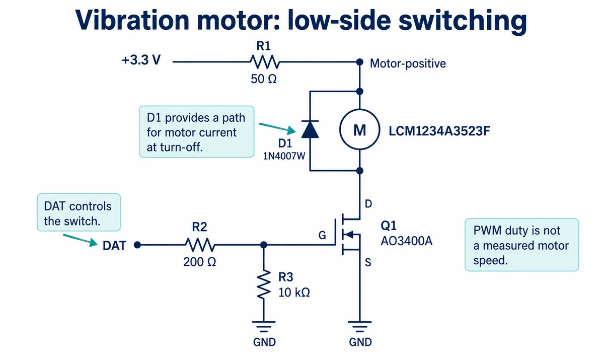
Our driver ran the PWM at 1 kHz with an input range of 0 to 1023, scaled by 64 into MicroPython's 16-bit duty call. The test ran three settings for two seconds each: about full duty, about 50% and about 39%. In plain MicroPython terms, the middle step is equivalent to:
from machine import Pin, PWM

motor = PWM(Pin(6), freq=1000)
motor.duty_u16(512 * 64)   # about 50% duty
The terminal labeled the middle setting "half speed," but we measured no speed. It is roughly half duty; neither motor speed nor perceived vibration is established as half the maximum. The driver's duty-setting function also did not update its stored on/off flag, so its state query is not feedback that the motor is actually running.
We held the module by hand, without an enclosure. Once you mount it, test the effect through the surface a person actually touches. A brief click and a sustained buzz are different requirements. TI's haptic implementation note, revised November 2021, explains why a rotating-mass motor takes time to start and stop, and why a simple one-direction FET drive cannot apply reverse-voltage braking. Do not present this module as equivalent to a crisp phone haptic actuator.
Before reproducing the board, resolve its component references: the module documentation names an LCM1234A3523F motor, while the attached motor datasheet specifies an XHXDZ-1020. The schematic also has a regulator part number that conflicts with its 3.3 V rail label. Those details change the voltage at the motor, and our demonstration does not settle them or establish a maximum usable vibration level.
See the difference: the LED
The LED module drives its LED through a transistor switch. GPIO6 drives the control input; the LED's power comes from the module supply through a current-limiting resistor. The test flashed the LED three times at one-second intervals, then toggled it on and off once.
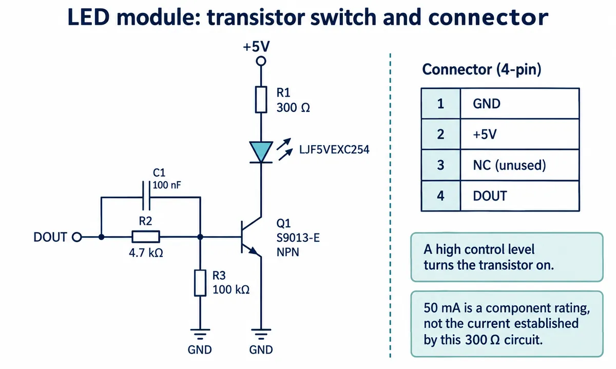
On camera the LED looked blue, while the LJF5VEXC254 datasheet linked from the module describes an orange part. Keep that distinction in mind when choosing a replacement: color, pin arrangement and optical behavior must match the fitted component.
The datasheet's 50 mA rating is not a measured current in our test. With a 300 ohm series resistor, the operating current depends on the supply, the LED's forward voltage and the transistor drop. For the first enclosure test, the useful question is whether people can see and interpret the light from the intended viewing position, including in bright surroundings, not whether the component has an impressive headline brightness.
Make the next prototype answer one question
These experiments give you three ideas to evaluate, not a reason to put every output in one product. Try a persistent light for status, a brief sound when attention is needed, or a vibration cue where the product is held. Compare them with people doing the actual task, then decide whether a combination helps. Give the user a clear way to acknowledge or silence a nonessential repeated cue.
If you combine modules, give each its own control output and account for their combined supply demand. Replace long blocking sequences if the device must stay responsive. Test boot-up, cancellation and the state after a task completes, then repeat with the enclosure assembled. We have not yet run a combined system or a user trial; those are the next checks.