
A desk device that looks clear in the workshop can feel painfully bright beside a bed. Turn it down for the evening and the display may disappear in daylight. An ambient-light sensor gives your prototype a way to respond, but a changing sensor number is only the beginning. You still need to decide how the device should change, and how to stop it changing too often.
We ran two bench experiments with GraftSense light modules on a GraftPort-RP2040 board under MicroPython. One used a GL5516 photoresistor to set up a relative dark-to-bright scale. The other read illuminance from a BH1750 over I2C. Neither is a finished automatic-brightness product. Together they show how to choose a useful input and what to check before wiring that input to the user interface.
Choose the behavior before choosing the number
Perhaps your prototype only needs two comfortable brightness settings. Or perhaps you need a light reading that you can log and compare between test sessions. Those are different requirements. For the first, a repeatable relative threshold may be enough; for the second, a lux-based measurement tells you more.
Even a shipping product with a light sensor can behave badly. In a Purism community discussion from July to September 2026, users described unreadable screens in sunshine and abrupt changes when moving between light and shade, and the follow-up included a manual brightness workaround. Keep a usable manual control while testing automation, so the sensor is never the only way to get a readable screen back.
So the design question is more specific than "Can we measure light?" It is "What should this device do when the room changes, and can the person still control it?" Start there, with a small set of real environments: a bright workbench, the intended indoor location and a dark room.
The photoresistor: teach it your dark and bright conditions
The GL5516 changes resistance with light. On this module it forms a divider with a fixed resistor, and an LM358 buffers the resulting voltage for an analog input. With the resistor on top of the divider, stronger light lowers the measured voltage, so a smaller raw number means a brighter environment.
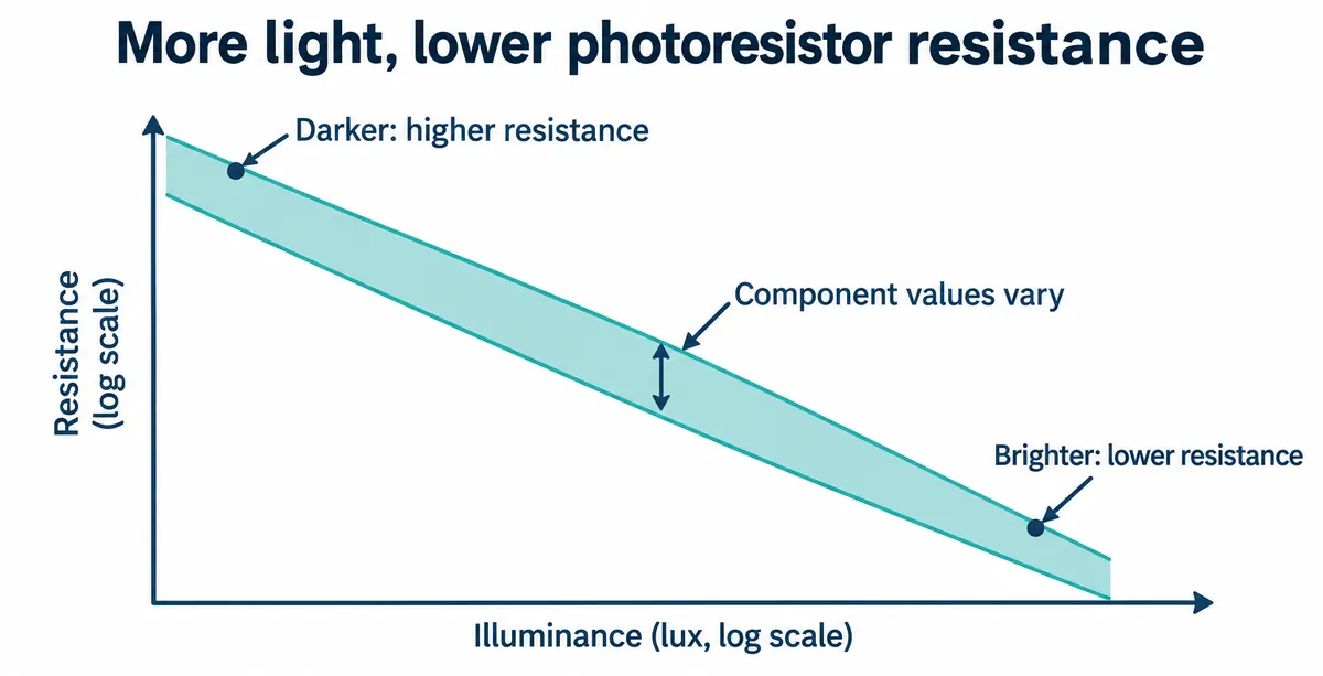
We connected the module to the AIN0 port, using GPIO 26 for the analog signal. The module takes a 5 V input with a regulated rail for the divider, and the amplifier is powered from 5 V. Verify the actual board and its output range before connecting it to another controller's ADC. "Works with a 5 V supply" does not mean every signal is safe for every input.
Our test program asked the user to place the sensor in low light and press Enter, then repeat in bright light. It stored the two raw readings as endpoints and mapped later readings between them as a percentage.
The recorded low-light endpoint was 39401 and the bright endpoint was 2768. The names describe the light conditions, not the numerical order: the driver deliberately maps the smaller, bright value toward 100%.
That percentage belongs to the two conditions you chose. It is not lux, and 50% does not mean half the daylight or half the perceived brightness. The driver also clamps values to 0 to 100%, so a reading stuck at an end can mean the current environment lies outside the calibration range. Calibrating again after fitting the cover means more than copying someone else's endpoints.
The driver takes separate ADC samples for voltage, raw reading and percentage, so small differences between the printed values are possible while the light changes. For logging, use one captured sample for any values you need to compare directly.
The digital sensor: read lux, then decide what it means
The BH1750 provides digital light measurements over I2C, so the controller does not measure an analog voltage. Lux describes illuminance at the sensor. It still does not tell you what screen brightness a person will find comfortable.
ROHM's BH1750FVI technical note describes the measurement modes, conversion and optical-window adjustment. Finer resolution does not make the complete device a calibrated light meter: placement, cover material and the light reaching the sensor still matter.
We connected SDA to GPIO 4 and SCL to GPIO 5 on I2C0. A switch on the board selects between the two supported addresses.
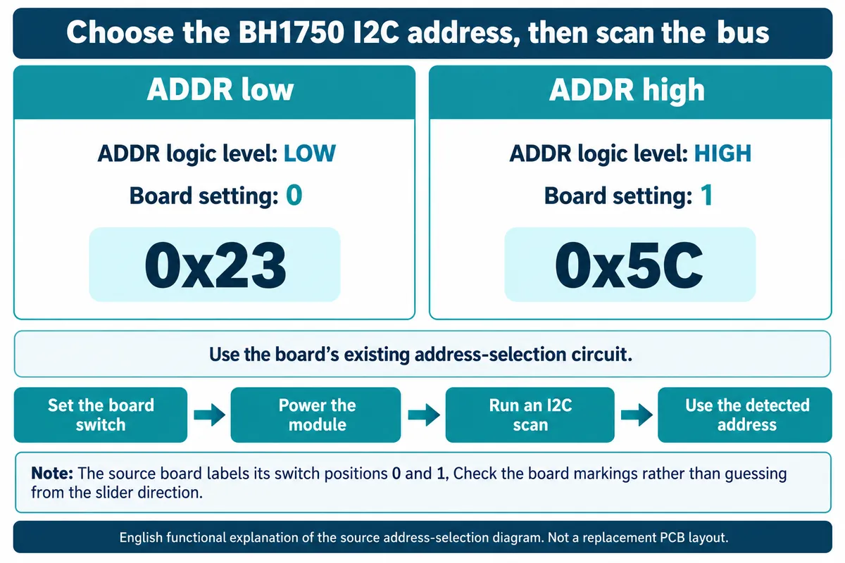
Our notes said 0x5C, but the scan reported 0x23. Use the setting and address on your actual assembly, and have the code accept only the two expected addresses rather than any device it finds. An I2C scan lists addresses that respond; it does not identify which part is answering.
The terminal showed readings from one-time, continuous and generator-based loops while we moved a handheld light over the module. That demonstrates a responsive readout. It is not agreement with a reference light meter, and because the light kept changing it is not a comparison of the modes either. The generator loop is just a software way to get successive readings, not a third sensing method.
Stay with the default measurement-time setting while you establish a baseline. The non-default measurement-time conversion and timing logic in the driver we used need correcting before those options are used for window compensation. Changing a sensitivity setting without checking the matching conversion can make a convincing-looking number wrong.
Keep the device from reacting to its own light
Once the sensor gives useful readings, mount it where it sees the environment you care about. A sensor beside a glowing indicator or behind the display window may mostly see the product itself. Test the reading with the display off, dim and bright while the room lighting stays the same.
A May 2025 Home Assistant discussion about lux-controlled cabinet lighting shows the same problem: when the lamp lights its own sensor, a single threshold can cause repeated on/off switching. The hardware differs, but the feedback path is the same.
For a two-state interface, use separate thresholds for entering and leaving the brighter mode. That gap, called hysteresis, keeps a small fluctuation around one boundary from reversing the decision again and again. You can also require a condition to last briefly before applying it. Choose those settings by watching the product in use; no single lux threshold makes every bedside display or exhibit comfortable.
For gradual adjustment, start with a few brightness levels that users have tried, move smoothly between them, and keep an easy manual override. These are integration steps beyond our experiments, to be evaluated with the real display, enclosure and users.
The photoresistor route is useful when you need relative conditions for one particular prototype. The BH1750 route fits when you want a lux-based input and a digital interface. Either way, success means people can read and comfortably use the device as conditions change, not just that the terminal prints changing values.