
You have connected an AGS02MA gas-sensor module, found it on the I2C bus and run the example. The terminal prints TVOC: 100 several times. Is that a fresh measurement, a sensor still settling, or a program reading the wrong thing?
This note is for the person bringing up that sensor on a prototype board. On our bench we connected a GraftSense AGS02MA module to a GraftPort carrier with a Raspberry Pi Pico, running MicroPython, and recorded its output. Below are the details that affect reproduction: a 20 kHz bus, a skipped warm-up wait, the five-byte response and the driver's resistance conversion. The goal is to decide whether the data path is ready for the application, not to compare room-monitor displays.
A discussion among ESPHome builders asks why air-sensor readings can look stuck and whether startup, placement or software is to blame. It covers other sensor models, so its replies are not AGS02MA fixes, but the debugging question is the same: establish what this device and driver are returning before changing the room or the display to make a number look plausible.
Our record contains a physical connection, a MicroPython program and changing terminal values. It does not include a controlled gas exposure or a reference instrument, so we can check the communication and interpretation without treating the readings as a calibrated measurement of any pollutant.
Reproduce the connection at the speed this sensor expects
The module connected to the carrier's I2C0 connector with a four-wire cable: SDA on GP4 and SCL on GP5. Those are controller GPIO numbers, not sensor lead numbers. We used MicroPython's SoftI2C at 20 kHz, and the scan found the default seven-bit address 0x1A, printed as decimal 26.
The low bus speed matters. The manufacturer specifies no more than 30 kHz, so a program copied from a faster I2C device can fail even when the wires look right. Check power, ground and pull-ups against the actual board circuit too; a sensor's supply range is not automatically the input range of a module with its own regulator.
We used version 1.0.0 of our AGS02MA driver package, which is derived from the MIT-licensed Adafruit CircuitPython AGS02MA driver by ladyada, with credit to Tom Øyvind Hogstad. Keep the driver version with the prototype record; a later package should be reviewed before you assume the same behavior.
Wait for a usable sample
Our test program defined a 120-second warm-up constant and printed a warm-up message, but never actually waited. The driver's constructor does not wait either. A printed message is not evidence that the sensor has warmed up. This shortened version makes the wait explicit and keeps the 20 kHz bus and ten-second read interval:
i2c = machine.SoftI2C(scl=machine.Pin(5), sda=machine.Pin(4), freq=20000)
ags = AGS02MA(i2c)
print("Warming up; no valid reading yet")
time.sleep(120)

while True:
    try:
        print("TVOC raw value:", ags.TVOC)
    except RuntimeError as error:
        print("Reading unavailable:", error)
    time.sleep(10)
It is a correction to review on the target board, not a new hardware result. A runtime error now produces "unavailable" instead of a reassuring zero.
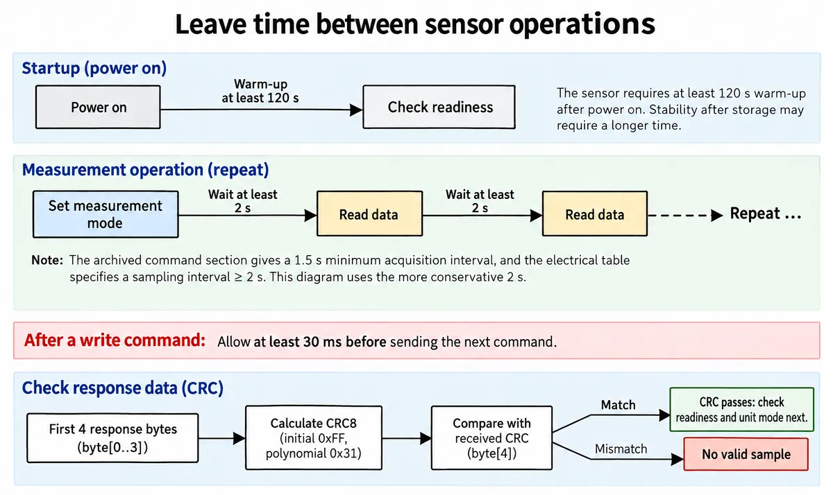
The AGS02MA datasheet lists at least 120 seconds of preheating and separately describes longer conditioning after storage, so two minutes is not a promise of stable readings in every case. For a user-facing prototype, keep a visible "warming up" state and confirm that readings settle under the intended operating conditions.
The driver also checks a CRC, a small checksum that detects a corrupted response, and a readiness bit. Those answer different questions: an intact message can still say new data is not ready. Our driver reports that condition as "still preheating," although the protocol also uses it for data that simply has not updated.
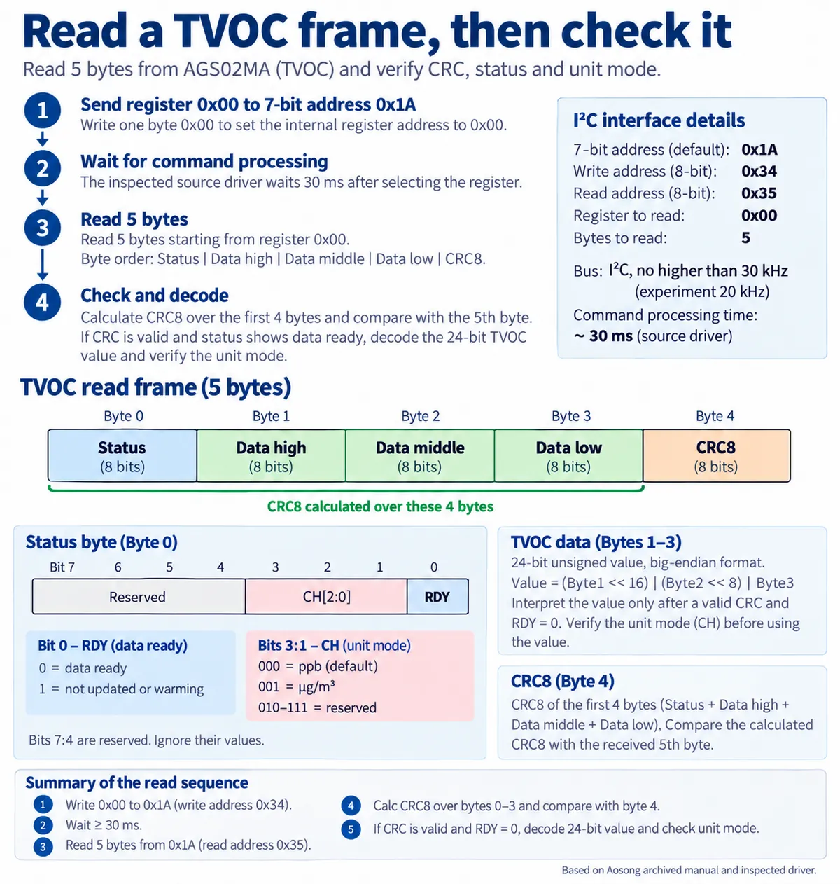
Unit labels need the same care. An older version of the manufacturer's manual describes both ppb and mass-concentration modes, while the later English manual presents ppb output. The driver's TVOC property returns the number without checking the unit-mode bits. Confirm the firmware and mode before printing "ppb" on a product screen, and do not convert an unidentified gas mixture to another unit with an arbitrary factor.
What the recorded readings tell us
Our terminal output began with Devices: [26], then showed several TVOC values of 100, followed by 240, 255, 269, 274, 293 and 288, with gas-resistance values changing alongside. That shows the setup obtained changing values. Without a controlled exposure, a reference concentration or the elapsed time behind the capture, it cannot tell us whether 100 represents a healthy room, what caused the later rise, or how accurate the values were.
The resistance printout is a second view of the sensing element, not a measurement of another pollutant. The driver multiplies the raw value by 100, and the manufacturer's raw unit is 0.1 kΩ, so the result is in ohms: 3716800 is about 3.72 MΩ. The package README labels that unit inconsistently, and copying its label to a dashboard would produce a large scaling error.
For the next run, add timestamps and short notes about ordinary changes in the room, and leave the monitor in a fixed position while comparing periods. Log an error as an error, and keep the time of the last valid sample if you leave it on screen, so a flat line can be told apart from a device that stopped updating.
Repeat the test under known operating conditions
A desk device has to let room air reach the sensor. Our open module had no housing; adding one changes that path. Place the sensor near a suitable opening, then compare its response in the housing with the open-board setup under comparable conditions.
The manufacturer also identifies strong direct airflow, moisture and contamination as factors that can disturb or damage this type of sensor. That affects vents, adhesives and cleaning processes. Do not seal the sensor behind a decorative panel or point a fan at it because it is mechanically convenient; follow the handling guidance for your part revision.
Before handing the sensor code to the rest of the project, save a short test record: board and driver version, supply arrangement, time since power-on, bus speed, the raw response when an error occurs, and timestamps for accepted samples. Repeat after a restart. If you add another I2C device, repeat with both running so the shared bus has not silently moved to a faster speed.
Once the data path is understood, decide what the user should see. The EPA's guidance on low-cost monitors explains why such a reading cannot describe every pollutant or replace an emergency alarm.