
Contents
- Introduction
- 1. Module Introduction
- 2. Introduction to Main Chips
- 2.1 Chip Overview
- 2.2 Pin Definitions
- 2.3 Functional Block Diagram
- 2.4 Performance Parameters
- 2.5 Reference Circuit
- 2.6 Chip Configuration
- 2.7 Communication Interfaces and Related Protocols
- 2.8 Register Definition
- III. Circuit Engineering
- 3.1 Circuit Source Project
- 3.2 Module Usage Instructions
- 3.3 Application Experiment
- 4. Driver
- 5. BOM & Recommended Alternatives
- 6. Change History
- VII. Related Materials
Introduction
In consumer scenarios such as steam oven water tanks, floor sweeping robot charging stations, coffee machines, or outdoor scenarios such as urban waterlogging and industrial equipment, the stability and accuracy of liquid level detection directly affect the user experience and safety of the equipment. However, traditional float-type and photoelectric liquid level solutions have always been unable to overcome the pain points of "easy jamming, easy misjudgment, and easy corrosion", causing frequent "hiccups" in the liquid level control of the equipment.
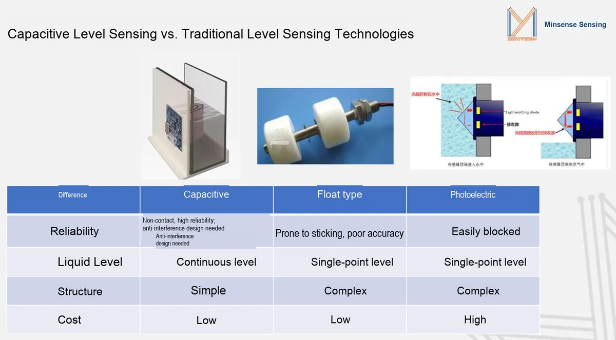
Traditional liquid level solutions each have their limitations: Float type is prone to being stuck by scale adhesion and only supports single-point liquid level detection; Photoelectric type is easily blocked by stains and water vapor, with a high error rate and relatively high cost; Contact electrode is easily affected by water quality, and data drift is severe after corrosion. In contrast, the capacitive solution relies on its core advantages of non-contact design, continuous liquid level detection, simple structure, and low cost to perfectly adapt to various scenarios: It does not need to contact the liquid and will not be contaminated by scale; It can achieve continuous liquid level monitoring from empty to full, supporting refined water volume control;The module has a simple structure, can be directly mounted on the outer wall of the container, is easy to install, and at the same time, its cost is much lower than that of the photoelectric solution, making it the preferred solution for consumer-grade and industrial-grade liquid level detection.
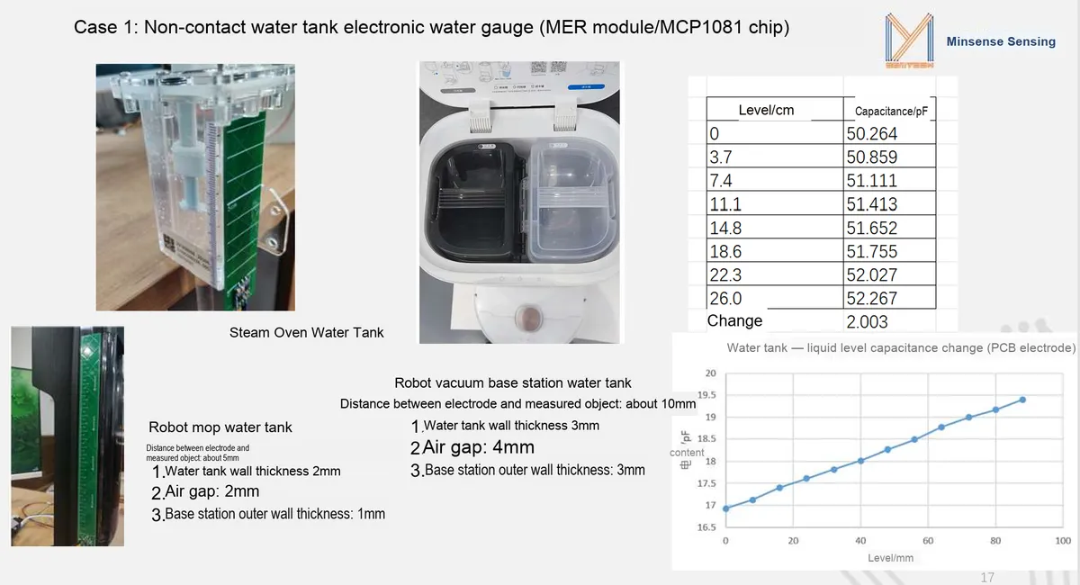
In outdoor scenarios such as urban waterlogging, tunnel water accumulation, and groundwater level monitoring, this module can serve as a non-contact liquid level detection unit, working in conjunction with a rain gauge to achieve full-process monitoring of rainfall - water accumulation - drainage. It is not affected by water impurities or changes in light, can operate stably in complex outdoor environments, output accurate liquid level data, provide reliable data support for urban waterlogging early warning and drainage scheduling, and contribute to enhancing the intelligent level of urban flood prevention management.
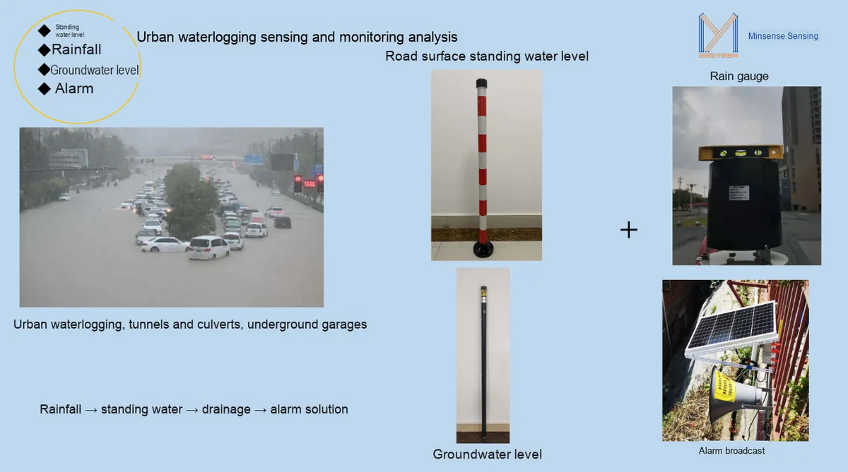
In the scenario of household appliance water tanks, sensors can be directly attached to the outer wall of the water tank, completing liquid level detection through the container wall without the need to come into contact with the liquid, thus completely avoiding corrosion or adhesion of the sensor caused by scale and oil stains. In the water tanks of devices such as steam ovens, floor cleaning robot charging stations, and coffee makers, it can stably output continuous liquid level data, enabling the device to accurately determine the water volume and avoid dry burning or overflow; even through a container wall of about 3mm and an air gap, it can maintain high sensitivity, perfectly adapting to the waterproof structural design of household appliances and providing a reliable basis for water volume control for the device.
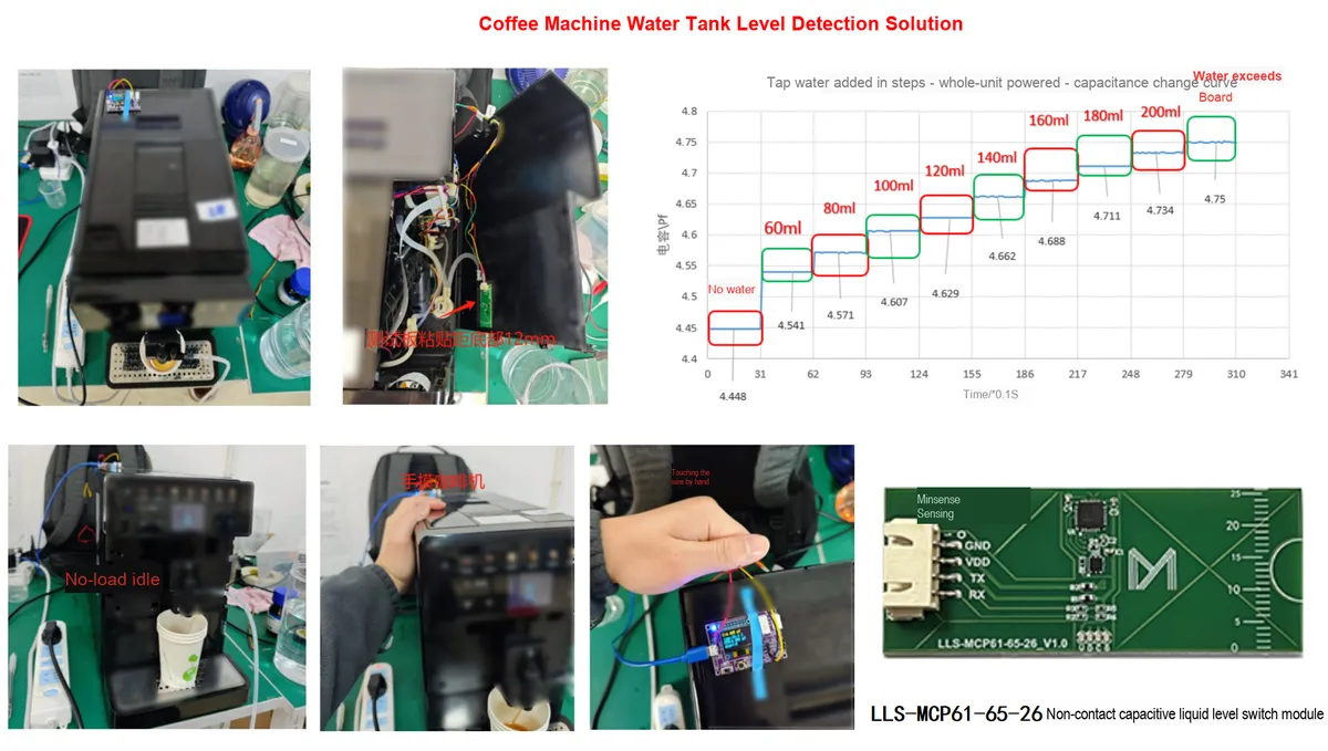
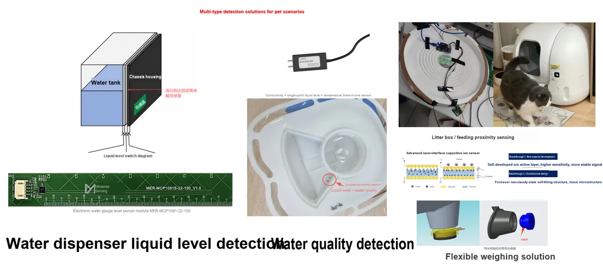
In the scenario of pet smart devices, it can not only be used for water tank level detection in water dispensers, but also extended to proximity sensing in cat litter boxes and remaining quantity detection in feeders. The non-contact installation method will not be contaminated by the stains from pet drinking water, continuous level detection can accurately reflect changes in water volume, and the low-power design also meets the long battery life requirements of pet devices, providing a stable and reliable sensing solution for pet smart devices and making pet drinking and feeding more intelligent.
1. Module Introduction
The Minyuan MER-MCP1081-260-26 Electronic Water Level Sensor is an intelligent liquid level detection module based on the capacitive non-contact measurement principle. It is equipped with the self-developed MCP1081S ten-channel multi-mode broadband digital capacitance processing chip, which realizes liquid level detection by sensing changes in the dielectric constant of the liquid without direct contact with the liquid. It can even perform measurements through non-metallic container walls such as plastic and glass, completely solving the industry problems of contact sensors being prone to corrosion, float sensors being prone to jamming, and photoelectric sensors being prone to occlusion. The built-in temperature compensation and anti-interference algorithms can effectively filter out interference caused by scale, water vapor, and temperature differences, output stable continuous liquid level data, and provide reliable liquid level sensing solutions for various scenarios.
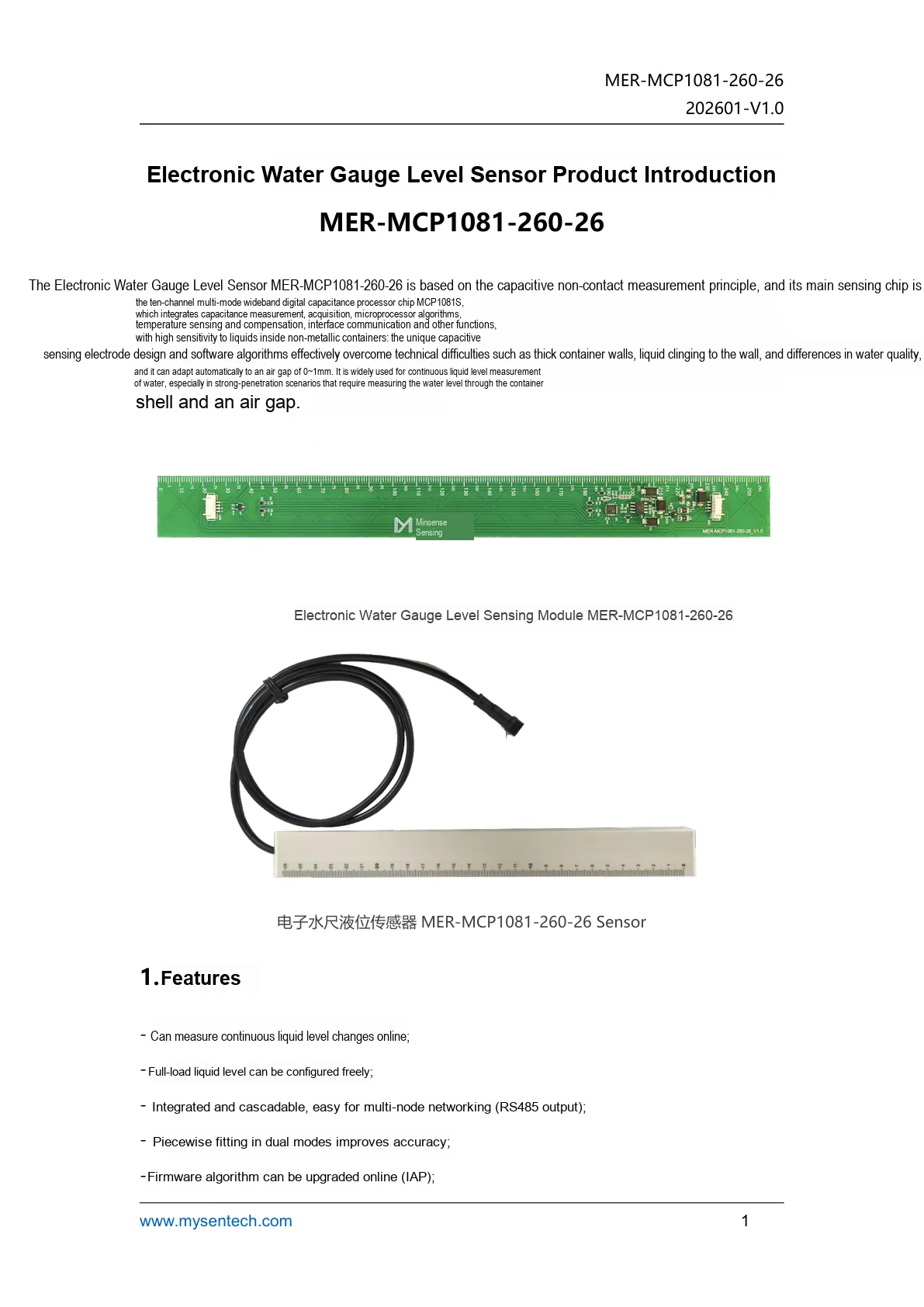
This figure shows the product introduction, appearance, and core feature description of the MER electronic water level gauge sensor.
- It can measure continuous/segmented liquid level changes, with the outer side of the sensor electrode surface marked with a scale for comparison with measured values at any time;
- Add temperature compensation, with a compensation range of 0°C to +50°C;
- Integrated, cascadeable, and easy to form multi-node networks;
- Add calibration parameter registers to facilitate users' self-calibration;
- Easy to install and low in cost.
2. Introduction to Main Chips
2.1 Chip Overview
MER-MCP1081-260-26 uses a ten-channel multi-mode broadband digital capacitive processor chip MCP1081S , which integrates capacitance measurement, acquisition, temperature sensing and compensation, microprocessor algorithms, and interface communication into one, enabling non-contact continuous detection of the internal liquid level of non-metallic containers.
2.2 Pin Definitions
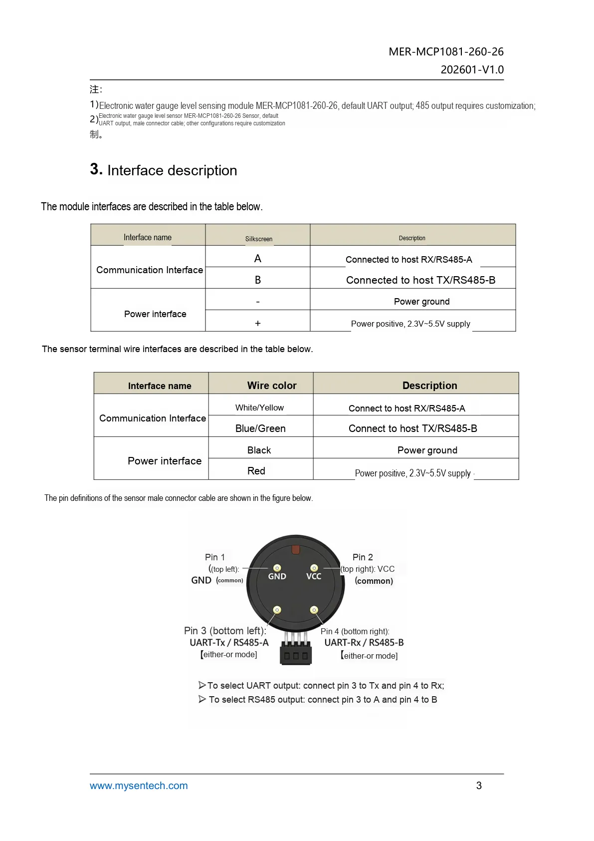
This diagram shows the interface definition of the MER module and sensors, which can be used to distinguish UART, RS485, and power pins.
2.3 Functional Block Diagram
None.
2.4 Performance Parameters
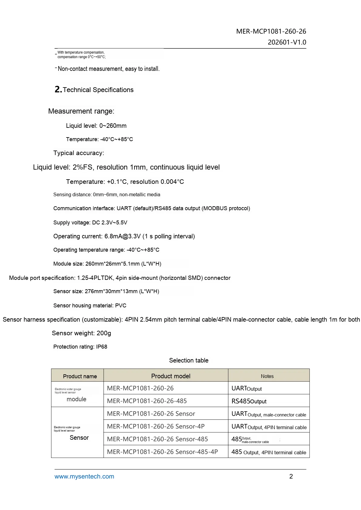
This figure lists the technical parameters of the MER module, including information such as range, accuracy, power supply, and interface type.
2.5 Reference Circuit
None.
2.6 Chip Configuration
None.
2.7 Communication Interfaces and Related Protocols
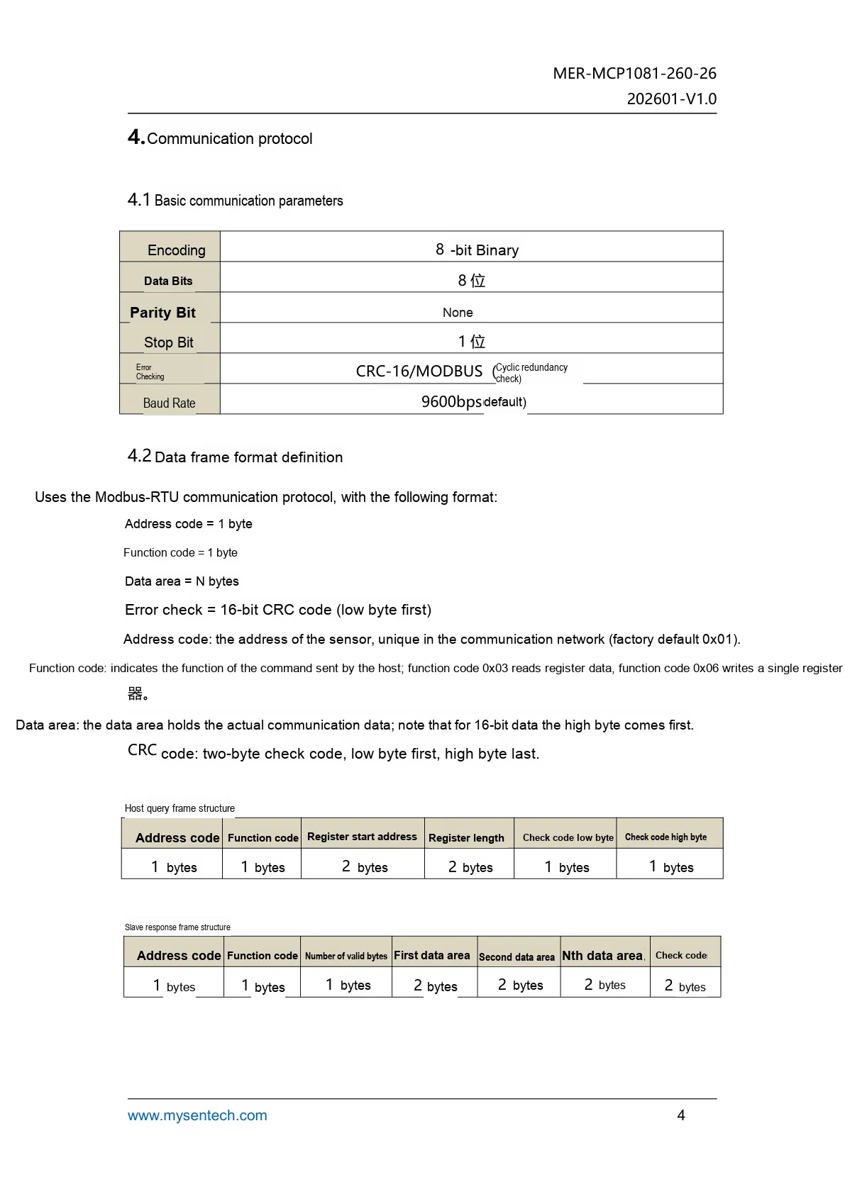
This figure shows the Modbus-RTU Communication Protocol and basic serial port parameters adopted by the MER module.
2.8 Register Definition
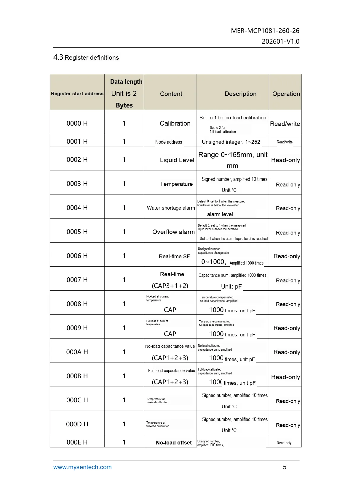
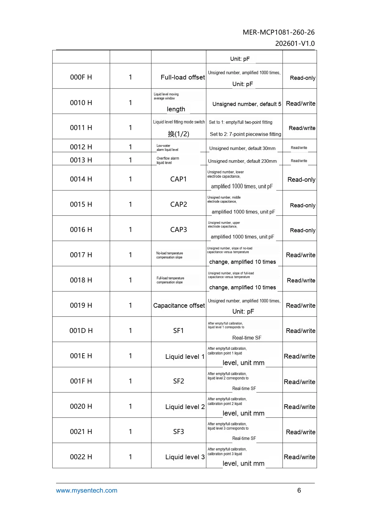
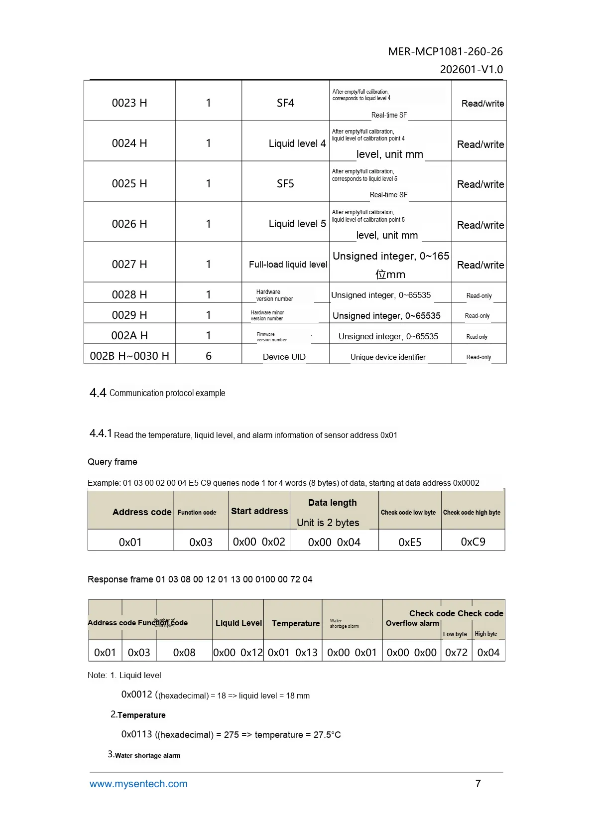
Displays register and calibration point configuration content, suitable for reference during high-precision liquid level calibration.
III. Circuit Engineering
3.1 Circuit Source Project
To obtain the circuit source project, please check the link below:
https://mysentech.com/productinfo/162716.html
3.2 Module Usage Instructions
3.2.1 Module Test Environment Setup and Precautions
When receiving the module, we first need to set up the test environment according to the following requirements:
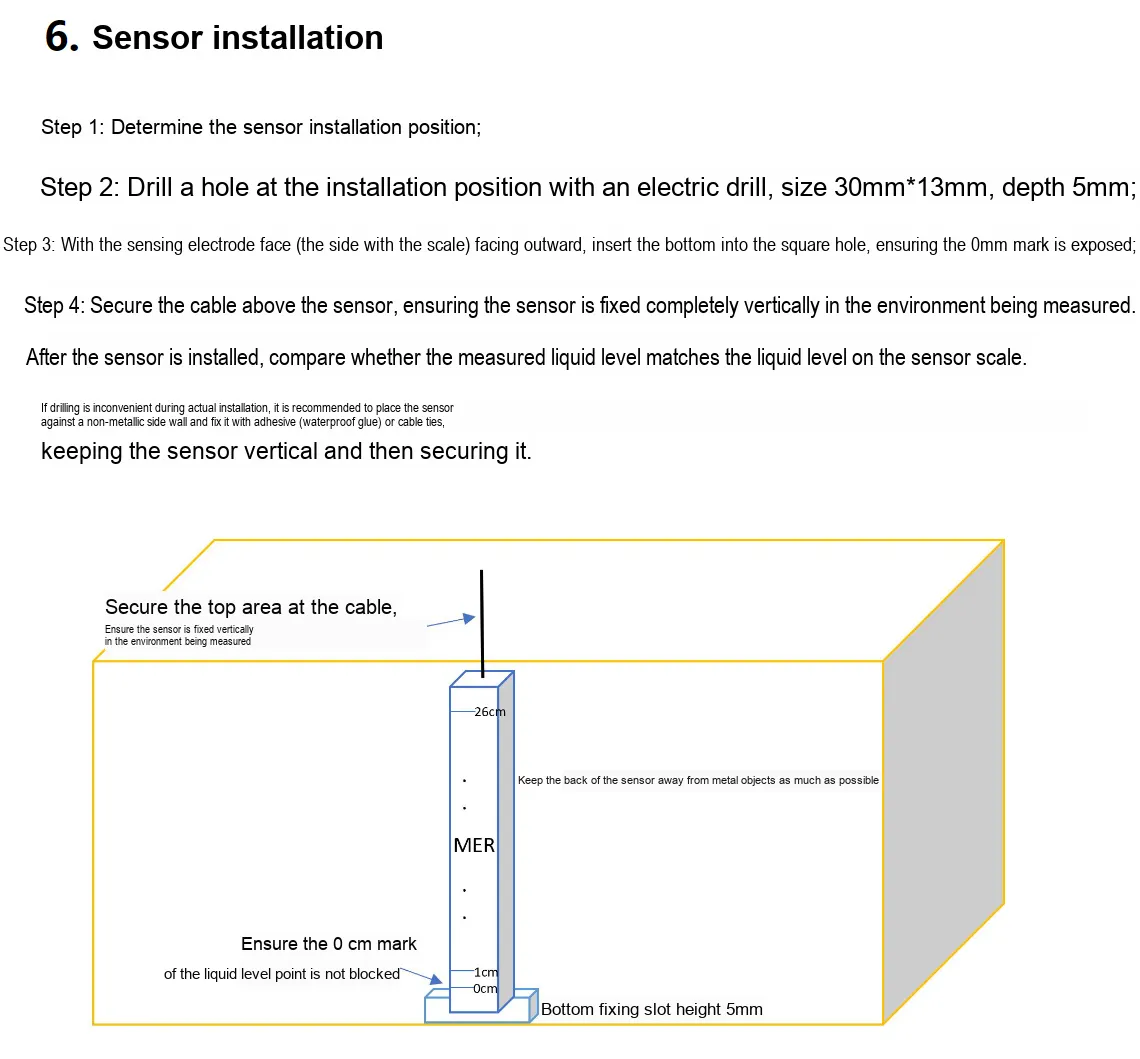
The non-contact penetration ability can be verified by directly simulating the liquid level scenario through a transparent plastic cup filled with water.
Note:
- The sensor must be installed vertically, with the 0 scale aligned with the bottom of the container, and the back side should be kept away from metal objects;
- During installation, try to be as close as possible to the non-metallic sidewall. For waterproof models, cable connectors must be properly protected. The power supply voltage is strictly prohibited from exceeding 5.5V to avoid damaging the module.
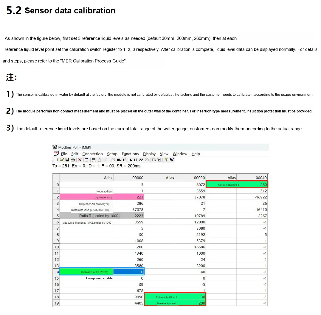
Next, proceed with the calibration according to the following steps:
3.2.2 Usage of Modbus Poll
Modbus Poll is a general-purpose Modbus master station debugging tool that is compatible with all capacitive sensors in this series that support the Modbus-RTU protocol. It can quickly achieve serial communication debugging between sensors and computers, real-time data reading, and log export, and is a general-purpose upper computer tool for verifying sensor functions and collecting test data. The software supports Modbus RTU/ASCII/TCP/IP protocols, is compatible with various register types and data formats, and its operation process is universal for all sensors in the series.
Before use, you need to complete the software installation and activation first. You can download the installation package through official channels. When opening it for the first time, you can try it for 30 days, or you can enter the registration code to activate it permanently. After connecting the sensor to the computer via hardware, open the software and click "Connection" - "Connect". In the pop-up window, configure the serial port parameters (Port Number, Baud Rate, Data Bits / Parity Bits / Stop Bits; sensors in this series default to 9600 Baud, 8N1 format, with the specific details subject to the corresponding model specification). After confirmation, you can establish a communication connection.
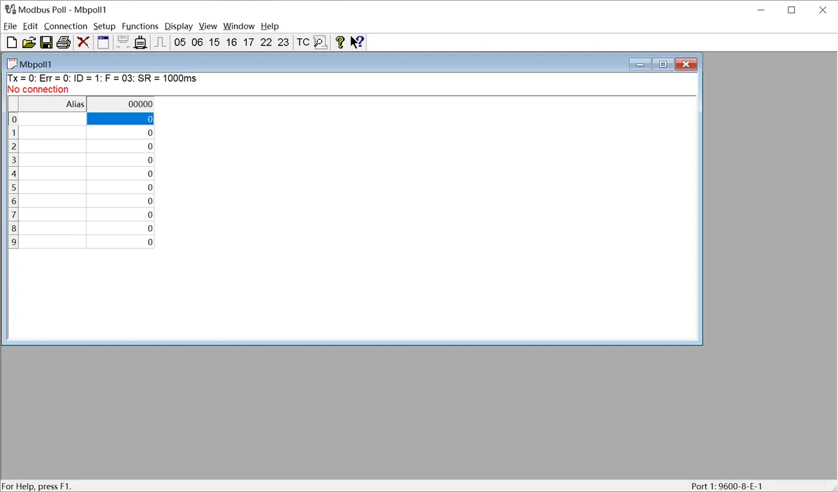
The following is a description of the general operating procedure:
- Serial Connection Configuration: After connecting the sensor to the computer via a USB-to-serial module, open the Modbus Poll software, click on the menu bar "Connection" - "Connect", select the COM Port Number corresponding to the sensor in the pop-up window, and configure the serial port parameters that match the sensor (Baud Rate, Data Bits, Parity, Stop Bits; sensors in this series default to 9600 Baud, 8N1 format). After confirmation, the communication connection can be established.
- Import Sensor Configuration File: The software supports importing the corresponding
.mbppre-configured files for each sensor model. The register address, data format, and alias definition have been pre-set in the file, eliminating the need for manual register configuration. Simply open the corresponding sensor's.mbpfile in the software, and all parameters will be automatically loaded. After a successful connection, the real-time detection data of the sensor (such as dust/rain/frost thickness values, status flags, etc.) will be directly displayed. - Data Logging (Optional): If you need to save test data, you can configure logging rules through the "Setup" - "Excel Log" function, which supports logging data at fixed intervals or every time data is updated, and allows you to set an upper limit on the number of records, facilitating subsequent analysis and verification of sensor data.
The above are the general basic operations of the host computer. For the pre-configured files, specific register definitions, and special configuration details of the .mbp of different sensor models, please refer to the content in "VII. Related Materials".
3.3 Application Experiment
Here, we use the GraftPort-RP2040 development board for testing, the MER-MCP1081-260-26 electronic water level sensor uses the UART interface to communicate with the main controller.
Here, we first use the HY2.0-4P connection cable to connect the module through the XH2.54-4P to HY2.0-4P interface module to the GraftPort-RP2040 development board's UART0 interface:
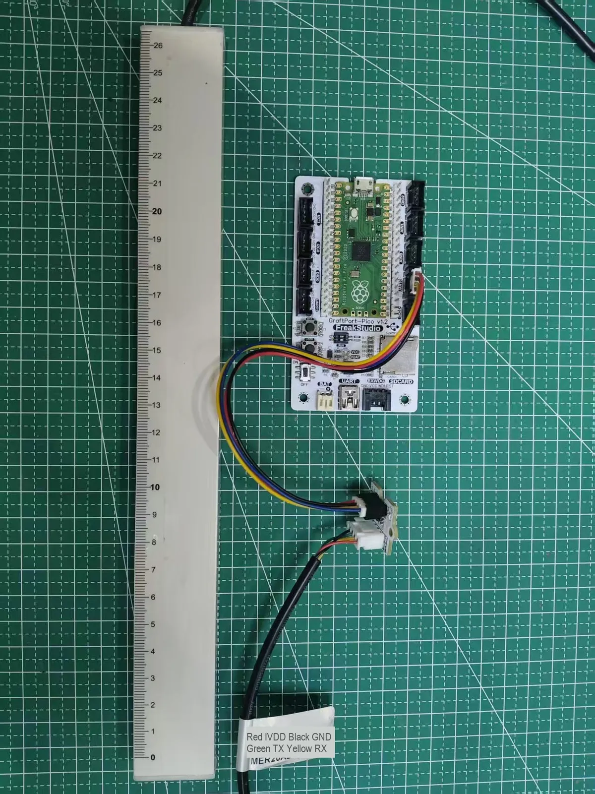
This diagram shows the wiring method between the MER module and GraftPort-RP2040 development board.
The module connections are shown in the following table:
Development Board Pins | Module Pin | Description |
Pin 16 |
|
|
Pin 17 |
|
|
Here, we need to search for relevant driver packages on uPyPI: https://upypi.net/zh/
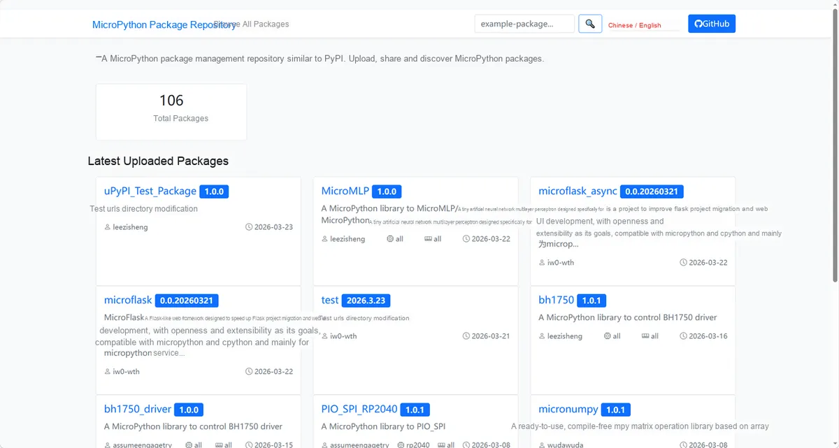
This figure demonstrates the operating interface for searching for the MER driver package in uPyPI.
Enter mcp_driver to search, and the results are as follows:
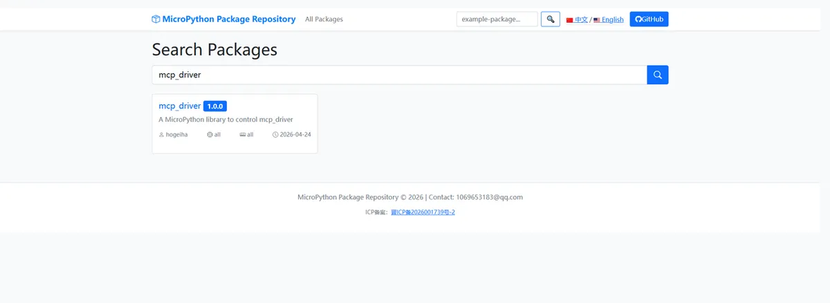
This figure shows the mcp_driver search results, facilitating the confirmation of the target driver package to be installed.
Click to copy the local installation command:
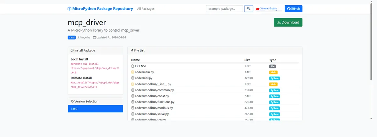
This figure shows the interface for copying the MER driver installation command, facilitating the rapid deployment of the test environment.
Import module driver library code via mip tool, the following are the usage instructions for mpremote tool:
mpremote mip install https://upypi.net/pkgs/mcp_driver/1.0.0After importing MER-MCP1081-260-26 Electronic Water Level Sensor - MicroPython Driver Code , copy the following main.py code into our project:
# Python env   : MicroPython v1.23.0
# -*- coding: utf-8 -*-
# @Time    : 2026/4/9 PM 6:02
# @Author  : hogeiha
# @File    : main.py
# @Description : MER electronic water gauge sensor initialization, parameter reading and real-time data acquisition loop program

# ======================================== Import Modules =========================================
# Import the MER electronic water gauge sensor driver class
from mer import MER

# Import the time module for delay control
import time

# ======================================== Global Variables ============================================
# Sensor Modbus slave address
SLAVE_ADDR = 1
# UART port number used
UART_ID = 0
# UART transmit pin
TX_PIN = 16
# UART receive pin
RX_PIN = 17

# ======================================== Functions ============================================

# ======================================== Custom Classes ============================================

# ======================================== Initialization configuration ===========================================
time.sleep(3)
print("FreakStudio: MER Water Level Sensor Running")

# Instantiate the MER electronic water gauge sensor object
sensor = MER(SLAVE_ADDR, UART_ID, TX_PIN, RX_PIN)
# Print sensor initialization complete message
print("=" * 50)
print("MER Electronic Water Level Sensor Initialized")
print("=" * 50)

# ========================================  Main Program  ============================================
# Read and print basic read-only device information
print("\n【Device Basic Info】")
# Read sensor node address
print(f"Current Node Address: {sensor.read_node_address()}")
# Read hardware version
print(f"Hardware Version: {sensor.read_hw_version()}")
# Read firmware version
print(f"Firmware Version: {sensor.read_fw_version()}")
# Read device unique identifier
print(f"Device UID: {sensor.read_device_uid()}")

# Read and print the sensor's read/write configuration parameters
print("\n【Configuration Parameters】")
# Read filter count parameter
print(f"Filter Count: {sensor.read_filter_count()}")
# Read low-power mode enable status
print(f"Low Power Enable: {sensor.read_low_power_enable()}")
# Read reference liquid level 1 value
print(f"Reference Level 1: {sensor.read_ref_level1()} mm")
# Read reference liquid level 2 value
print(f"Reference Level 2: {sensor.read_ref_level2()} mm")
# Read reference liquid level 3 value
print(f"Reference Level 3: {sensor.read_ref_level3()} mm")

# Example code for modifying configuration parameters, enable as needed
# Change filter count to 10
# sensor.write_filter_count(10)
# Enable low-power operating mode
# sensor.write_low_power_enable(1)
# Change sensor node address to 2
# sensor.write_node_address(2)

# Example code for sensor calibration, enable as needed
# print("\n【Start Calibration】")
# sensor.write_ref_level1(30)
# sensor.write_calib_switch(1)
# time.sleep(1)
# sensor.write_ref_level2(70)
# sensor.write_calib_switch(2)
# time.sleep(1)
# sensor.write_ref_level3(100)
# sensor.write_calib_switch(3)
# print("Calibration Completed")

# Loop to read real-time sensor data
print("\n【Real-time Data Reading Loop】")
while True:
    # Read liquid level data
    level = sensor.read_level()
    # Read temperature data
    temp = sensor.read_temp()
    # Read capacitance data
    cap = sensor.read_capacitance()
    # Read ratio data
    ratio = sensor.read_ratio()
    # Read frequency data
    freq = sensor.read_frequency()

    # Print the various real-time acquired data
    print(f"Level: {level} mm | Temperature: {temp} ℃ | Capacitance: {cap} pF | Ratio: {ratio} | Frequency: {freq} MHz")
    # Read data once every 1 second
    time.sleep(1)
Burn the code, open the terminal, and the output is as follows:
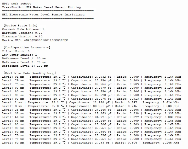
This figure shows the serial port output results of the MER example program, which can verify that the reading of parameters such as liquid level, temperature, and capacitance is normal.
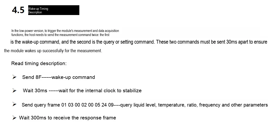
Here, note that the wake-up operation is already built into our driver library, so developers do not need to perform secondary operations.
4. Driver
mcp_driver.zip 47 KB
5. BOM & Recommended Alternatives
None.
6. Change History
Document Version | Modification Date | Modifier | Modified Content |
v1.0 | 2026-04-24 | Hou Junhan | Initialize Document |
v1.1 | 2026-05-20 | Li Zisheng | Add Introduction, 3.2.2 Usage of Modbus Poll |
VII. Related Materials
MER Electronic Water Gauge Liquid Level Sensor Product Introduction-MSE202412.pdf 958 KB