Contents
- 1. Module Introduction
- 2. Introduction to Main Chips
- 2.1 Chip Overview
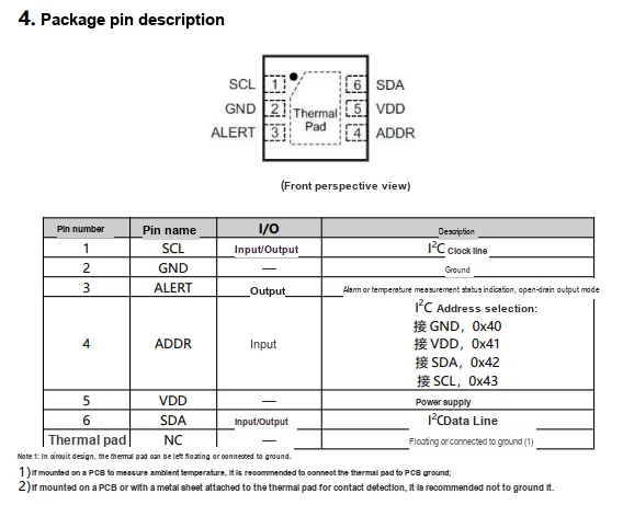
- 2.2 Pin Definitions
- 2.3 Functional Block Diagram
- 2.4 Performance Parameters
- 2.5 Reference Circuit
- 2.6 Chip Configuration
- 2.7 Communication Interfaces and Related Protocols
- 2.8 PCB Wiring Precautions
- III. Circuit Engineering
- 3.1 Circuit Source Engineering
- 3.2 Module Usage Instructions
- 3.3 Application Experiment
- 4. Driver
- 5. BOM & Recommended Alternatives
- 6. Change History
- VII. Related Materials
- 7.1 Chip Data Sheet
- 7.2 Special Icons for PCB Silk Screen
1. Module Introduction
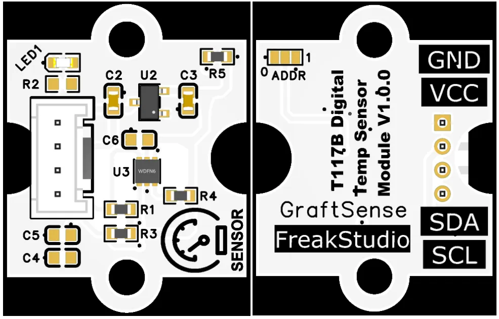
Digital temperature sensor module based on T117B, using Minyuan Sensing T117B high-precision digital temperature sensor solution, compatible with TI TMP117, based on PN junction/bandgap principle, with built-in 16-bit ADC, capable of directly outputting temperature data;The module is equipped with an address selection circuit, LDO voltage regulator circuit, power supply filtering and indicator light circuit, powered by 3.3V and supporting I²C and single-bus dual-protocol communication. The temperature measurement range covers -103°C to +153°C, with an accuracy of ±0.5°C in the 0-60°C range, a resolution as high as 0.004°C, extremely low power consumption, and is suitable for high-precision temperature measurement scenarios in industries such as industrial, medical, and energy storage.
2. Introduction to Main Chips
2.1 Chip Overview
2.2 Pin Definitions
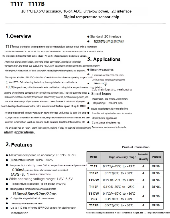
T117B is a digital temperature sensor chip with I²C interface from Minyuan Sensing, using DFN6L package, with a temperature measurement range of -103°C to +153°C, an accuracy of ±0.5°C in the range of 0°C to +60°C, a 16-bit ADC resolution of 0.004°C, featuring ultra-low power consumption, self-diagnosis, and alarm functions, suitable for scenarios such as smart wearables, medical, and cold chain.
2.3 Functional Block Diagram
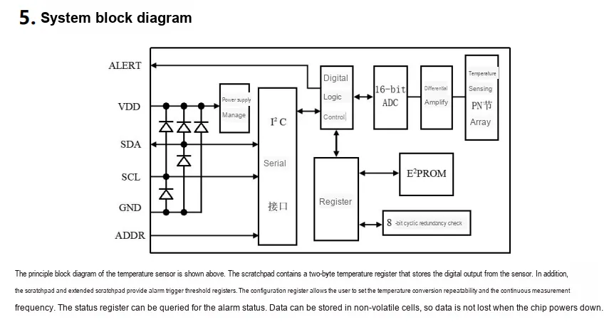
T117 series chips collect temperature signals through a temperature-sensing PN junction array, which are then amplified differentially and sent to a 16-bit ADC for conversion into digital signals. Subsequently, they are processed by digital logic control. Data can be temporarily stored in registers and written to E²PROM to achieve non-volatile storage. The chips communicate with the outside world via I²C serial interface, while integrating power management and ALERT alarm functions. Users can set the conversion frequency and alarm threshold through configuration registers to achieve high-precision, low-power temperature detection and monitoring.
2.4 Performance Parameters
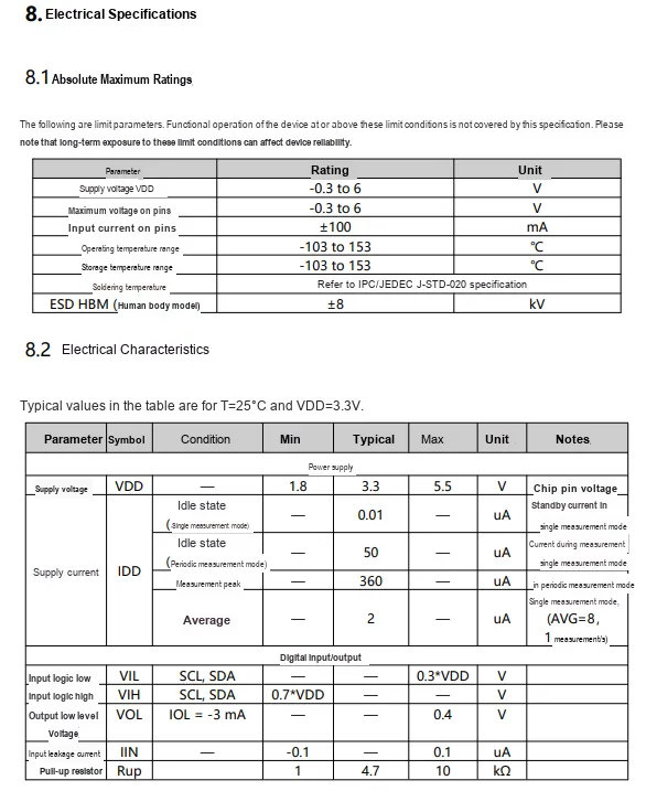
T117 has a supply voltage range of 1.8V to 5.5V, an operating/storage temperature range of -103°C to +153°C, HBM mode ESD protection of ±8kV; in terms of electrical characteristics, in single measurement mode, the typical standby current is 0.01μA and the average current is only 2μA, I²C interface supports standard logic levels, and the recommended pull-up resistor is 1 to 10kΩ.
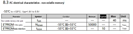
Under the power supply conditions of -55°C to +125°C and 1.8V to 5.5V, its E²PROM has a maximum write cycle of 40ms, a minimum number of erasable and writable times of 50,000, and a typical data retention time of 10 years.
2.5 Reference Circuit
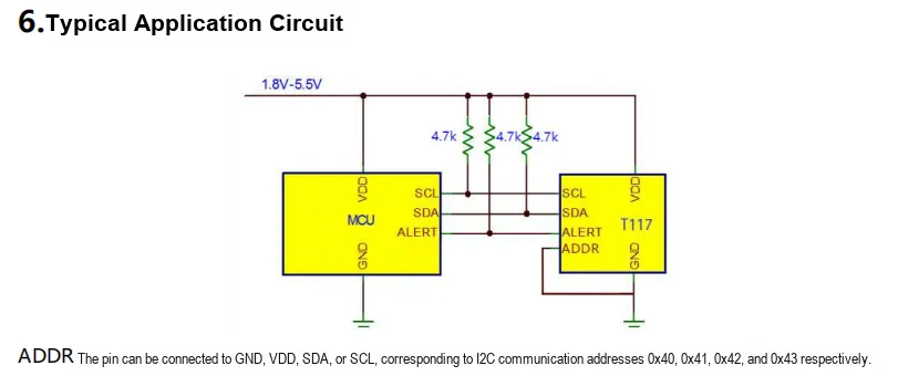
T117 communicates with MCU via I²C bus, SCL, SDA lines are each externally connected with a 4.7kΩ pull-up resistor, and the power supply is 1.8V - 5.5V; ADDR pin is grounded to set the I²C address to 0x40, ALERT pin is directly connected to MCU to implement the hardware triggering of temperature alarm signals, and the overall circuit completes the reading of temperature data and alarm function through the standard I²C protocol.
2.6 Chip Configuration
None.
2.7 Communication Interfaces and Related Protocols
2.7.1 Temperature Calculation
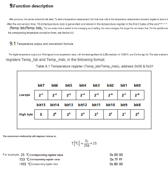
2.7.2 Register
2.7.2.1 Instruction Register
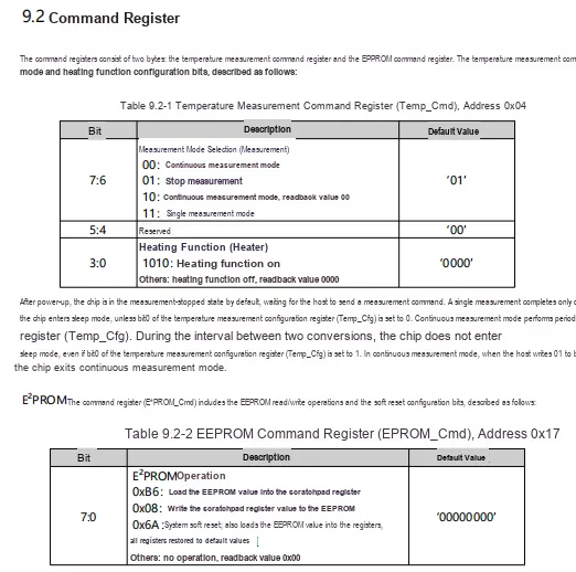
T117's instruction register, the temperature measurement instruction register (address 0x04) can configure the measurement mode (single / continuous / stop) and heating function, with the chip defaulting to stop measurement; E²PROM instruction register (address 0x17) supports E²PROM read/write, soft reset and other operations, enabling the storage and restoration of configurations.
2.7.2.2 Configuration Register
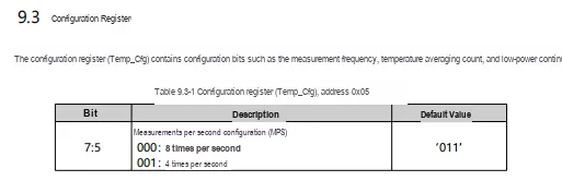
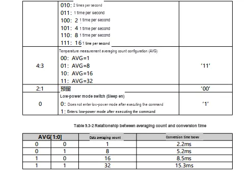
T117's configuration register (address 0x05) can configure the periodic measurement frequency (8 times per second to 1 time per 16 seconds, default 1 time per second), the number of temperature measurement averages (1/8/16/32 times, default 32 times, corresponding to a conversion time of 2.2~15.3ms), and the low-power mode switch (default enabled, entering low-power mode after command execution), thereby flexibly adjusting the measurement rate, accuracy, and power consumption.
2.7.2.3 Status Register
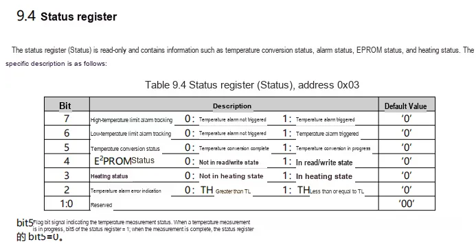
T117's status register (address 0x03) is in read-only mode, containing information such as temperature high and low line alarm status, conversion status, E²PROM read/write status, heating status, and alarm threshold configuration error indication, etc., which can be used to query the operating status of the chip.
2.7.2.4 Register List
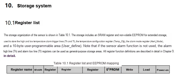
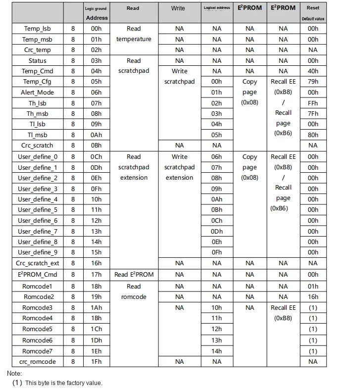
2.7.3 I2C Communication
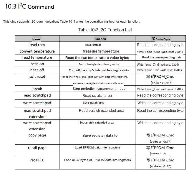
T117 series chips' I²C commands support functions such as reading ROM, temperature measurement, temperature reading, heating control, soft reset, cycle measurement stop, scratch area read/write, register data and E²PROM mutual copying, etc. Corresponding operations are triggered by writing commands to registers such as Temp_Cmd (0x04), E²PROM_Cmd (0x17), etc.
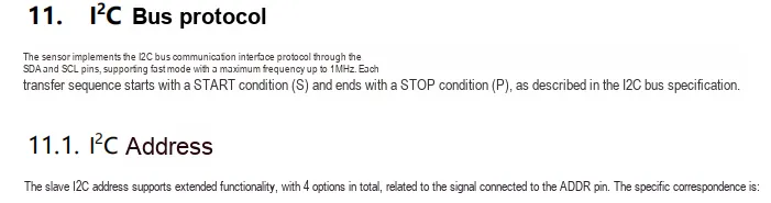
T117 sensor implements I²C communication via SDA/SCL pins, supporting a fast mode up to 1MHz. Communication starts with a START condition and ends with a STOP condition; its slave address can be configured via the ADDR pin, providing a total of 4 optional addresses and supporting multi-device bus expansion.
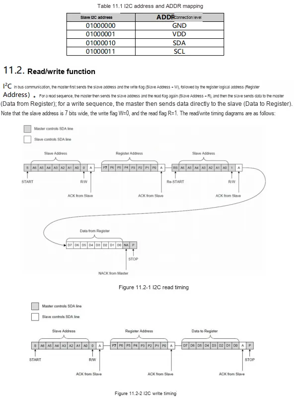
T117's I²C slave address can be configured via the ADDR pin level (connected to GND/VDD/SDA/SCL respectively corresponding to different addresses), and read and write communication follows the standard I²C timing: read operations require first sending the write address + register address, then switching to the read address via a repeated start to read data; write operations sequentially send the write address, register address, and data, during which the slave ACK response is required.
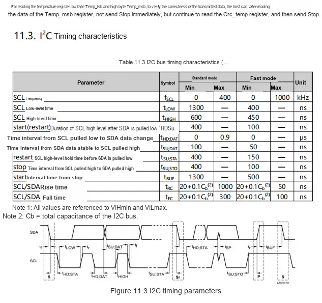
T117 series I²C bus supports Standard Mode (up to 400kHz) and Fast Mode (up to 1000kHz), specifying timing parameters such as SCL high and low levels, start/stop signals, data setup/hold, etc.; after the host reads the temperature data, it can verify the correctness of the transmission by reading the Crc_temp register.
2.8 PCB Wiring Precautions
None.
III. Circuit Engineering
3.1 Circuit Source Engineering
ProPrj_Digital Temperature Sensor Module Based on T117B_v1.0.0_2026-05-12.epro2 2.8 MB
Digital Temperature Sensor Module Based on T117B-V1.0.0.rar 3.2 MB
3.2 Module Usage Instructions
The schematic diagram of this module is as follows:
SCH_Schematic1_Digital Temperature Sensor Module Based on T117B_v1.0.0_2026-05-12.pdf 2.2 MB
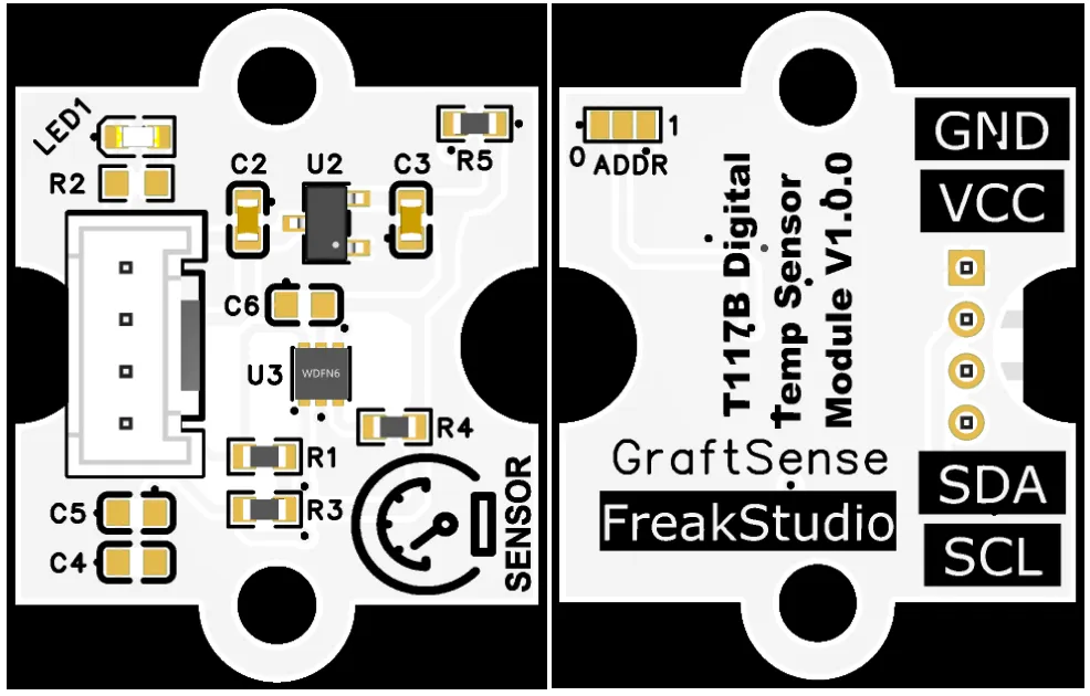
This module provides IIC communication interface: supports standard I2C communication rate, through ADDR pin can be flexibly configured I2C address, compatible with 3.3V level, can stably transmit T117B high-precision digital temperature data collected, temperature measurement range covers - 103℃~+153℃, suitable for high-precision temperature measurement scenarios such as industrial, medical, energy storage, etc., providing the system with reliable ultra-wide temperature range, low-power temperature sensing data interaction capabilities.
3.3 Application Experiment
Here, we use the GraftPort-RP2040 development board for testing, and the digital temperature sensor module based on T117B uses the I2C interface to communicate with the master.
Here, we first use the HY2.0-4P connection cable to connect the module to the GraftPort-RP2040 development board's I2C0 interface:
Module connections are shown in the following table:
Development Board Pins | Module Pin | Instructions |
Pin 4 |
|
|
Pin 5 |
|
|
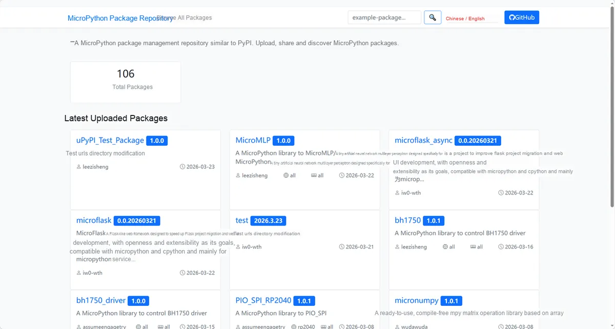
Here, we need to search for relevant driver packages on uPyPI:https://upypi.net/zh/
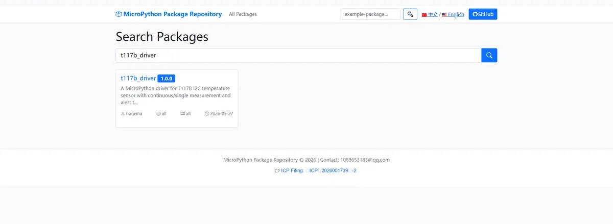
Enter t117b_driver for search, and the display is as follows:
Click to copy the local installation command:
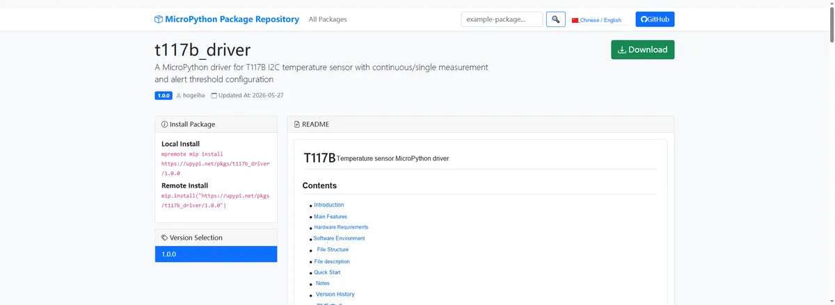
Import module driver library code via mip tool, the following are the usage instructions for mpremote tool:
mpremote mip install https://upypi.net/pkgs/t117b_driver/1.0.0After importing the MicroPython driver code for the T117B-based digital temperature sensor module, copy the following main.py code into our project:
# Python env   : MicroPython v1.23.0
# -*- coding: utf-8 -*-
# @Time    : 2026/05/26 12:00
# @Author  : hogeiha
# @File    : main.py
# @Description : Code for testing the T117B temperature sensor driver class
# @License : MIT

# ======================================== Import Modules =========================================
from machine import I2C, Pin
from t117b import T117
import time

# ======================================== Global Variables ============================================
# T117B target I2C address (ADDR pin connected to VDD)
DEVICE_ADDR    = [0x40,0x41,0x42,0x43]
# ROM ID register base address (used for device identification)
REG_ROM_ID     = 0x18
# Print interval (ms)
PRINT_INTERVAL = 500
# Alert high-temperature threshold (℃)
ALERT_TH       = 30.0
# Alert low-temperature threshold (℃)
ALERT_TL       = 10.0

# ======================================== Functions ============================================
def scan_i2c(i2c: I2C) -> int:
    """Scan the I2C bus and return the target device address"""
    # Scan all devices on the bus
    devices = i2c.scan()
    if not devices:
        raise RuntimeError("No I2C device found on bus")
    print("I2C devices found: %s" % [hex(d) for d in devices])
    # Look for the target address
    for addr in devices:
        if addr in DEVICE_ADDR:
            print("Target device found at 0x%02X" % addr)
            return addr
    raise RuntimeError("Device not found at expected address 0x%02X" % DEVICE_ADDR)


def read_rom_id(i2c: I2C, addr: int) -> None:
    """Read the ROM ID register and print it (T117B has no standard WHO_AM_I, printed for reference only)"""
    try:
        rom_id = i2c.readfrom_mem(addr, REG_ROM_ID, 4)
        print("ROM ID: %s" % [hex(b) for b in rom_id])
    except OSError as e:
        print("ROM ID read failed: %s" % str(e))


def test_basic_read(sensor: T117) -> None:
    """Test basic temperature reading"""
    temp = sensor.get_temp()
    status = sensor.get_status()
    print("Temperature: %s C  Status: %s" % (temp, status))


def test_boundary_params(sensor: T117) -> None:
    """Test boundary parameters: extreme threshold configuration"""
    # Extreme high-temperature threshold 130℃, extreme low-temperature threshold -100℃
    sensor.set_alert_thresholds(130.0, -100.0)
    print("Boundary thresholds set: TH=130.0, TL=-100.0")
    # Restore normal thresholds
    sensor.set_alert_thresholds(ALERT_TH, ALERT_TL)
    print("Thresholds restored: TH=%s, TL=%s" % (ALERT_TH, ALERT_TL))


def test_invalid_params(sensor: T117) -> None:
    """Test invalid parameters: verify that ValueError is raised correctly"""
    # Test invalid thresholds with th <= tl
    try:
        sensor.set_alert_thresholds(10.0, 30.0)
        print("ERROR: Expected ValueError not raised")
    except ValueError as e:
        print("ValueError raised as expected: %s" % str(e))
    # Test invalid avg value
    try:
        sensor.set_avg(99)
        print("ERROR: Expected ValueError not raised")
    except ValueError as e:
        print("ValueError raised as expected: %s" % str(e))
    # Test invalid mps value
    try:
        sensor.set_mps(8)
        print("ERROR: Expected ValueError not raised")
    except ValueError as e:
        print("ValueError raised as expected: %s" % str(e))


# ======================================== Custom Classes ============================================

# ======================================== Initialization ==========================================
time.sleep(3)
print("FreakStudio: Using T117B temperature sensor ...")

# Initialize I2C bus
i2c = I2C(0, scl=Pin(5), sda=Pin(4), freq=400000)

# Scan and verify the device
driver_addr=scan_i2c(i2c)
read_rom_id(i2c, driver_addr)

# Instantiate the sensor driver
sensor = T117(i2c=i2c, addr=driver_addr)

# Configure alert: triggers when temperature exceeds ALERT_TH or falls below ALERT_TL
sensor.enable_alerts(th_temp=ALERT_TH, tl_temp=ALERT_TL,
                     mps=T117.MPS_2_1, avg=T117.AVG_8)
print("Alert configured: TH=%s C, TL=%s C" % (ALERT_TH, ALERT_TL))

# Run parameter validation tests (executed only once at initialization)
test_boundary_params(sensor)
test_invalid_params(sensor)

# Record the last print time
last_print_time = time.ticks_ms()

# ========================================  Main Program  ===========================================
try:
    while True:
        current_time = time.ticks_ms()
        # Read temperature and alert status at the print interval
        if time.ticks_diff(current_time, last_print_time) >= PRINT_INTERVAL:
            test_basic_read(sensor)
            last_print_time = current_time
        time.sleep_ms(10)

except KeyboardInterrupt:
    print("Program interrupted by user")
except OSError as e:
    print("Hardware communication error: %s" % str(e))
except Exception as e:
    print("Unknown error: %s" % str(e))
finally:
    print("Cleaning up resources...")
    sensor.deinit()
    del sensor
    print("Program exited")
Burn the code, open the terminal, and the output is as follows:
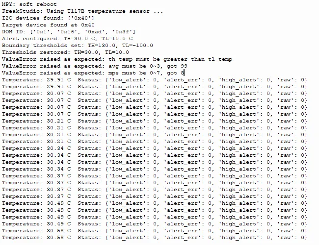
T117B Temperature Sensor I2C communication and initialization are normal, with complete functional verification:
- The base temperature data is stable, with readings ranging between 29.91°C and 30.58°C, varying slightly with the environment;
- Threshold configuration, parameter verification (such as
th_temp > tl_temp,avg/mpsrange) all triggered error prompts as expected; - Alarm status (
low_alert/high_alert/alert_err) all being 0 indicates that the current temperature has not triggered the high or low temperature thresholds, and the operating state is stable.
4. Driver
t117b_driver-1.0.0.zip 12 KB
5. BOM & Recommended Alternatives
BOM_Digital Temperature Sensor Module Based on T117B_v1.0.0.xlsx 12 KB
ModAcc_Digital Temperature Sensor Module Based on T117B_v1.0.0.xlsx 10 KB
6. Change History
Document Version | Modification Date | Modifier | Modified Content |
v1.0 | 2026-05-12 | Linggaoxing | Initialize Document |
VII. Related Materials
7.1 Chip Data Sheet
T117B.pdf 1.3 MB
7.2 Special Icons for PCB Silk Screen