
You have a controller on the workbench. Now you want a button on one side of an interactive room to change a light on the other, while a second light stays as it is. The first wireless milestone is getting a message across. The more useful one is knowing which device sent it, which device should act, and what happens when a device disappears.
On our bench we ran short-message tests with two GraftSense CC2530 radio modules on a GraftPort-RP2040 controller, then added a third module for node-to-node traffic. This note covers those tests, including an addressing problem they exposed, and what belongs in a first multi-node prototype.
Building your own network, or joining someone else's?
The modules carry CC2530-A1 radios with vendor firmware that accepts serial commands. The controller talks to each radio over a UART, a wired serial link, and the radio firmware handles the wireless side.
That is convenient for a small self-contained experiment. It does not make the modules compatible with a smart-home hub. A chip name identifies hardware; the firmware and the messages it understands decide how it fits into a system. Home Assistant's ZHA documentation lists supported radios and firmware, and describes older CC2530/CC2531 coordinators as supported but no longer recommended.
If your prototype must join an existing home-automation system, make that a separate acceptance test with the intended hub. If you control both ends of a small installation, the experiments below help you develop the message flow first.
Give each radio a role before giving it a message
In this firmware, one coordinator starts the network. A router joins and can relay traffic as well as send its own. An end device talks through a parent without forwarding others' traffic, which is what makes a sleeping sensor possible with suitable firmware. TI's Z-Stack overview explains these roles. We used only a coordinator and routers, not a battery-powered end device.
The vendor's transparent mode also has a direction. Plain serial data entering the coordinator goes to all nodes; plain data entering a node goes to the coordinator.
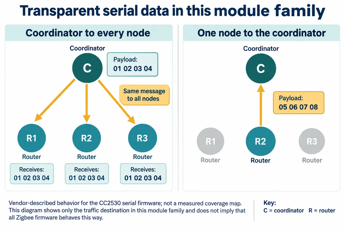
That suits collecting readings or sending a shared announcement. It is a poor default for a command meant to change one exhibit light.
The PAN ID identifies the network and the channel selects its frequency; neither is a device's individual address, and neither is related to the 9600 baud UART setting. Before coding, write down who starts the network, which devices have continuous power, and whether each message goes to everyone or to one destination.
The bench setup
Both modules connected to the controller by four-wire cables. The module schematic shows a nominal 5 V input feeding an AMS1117-3.3 regulator, with 3.3 V radio circuitry and 3.3 V serial logic. The module supply connection and a bare radio's supply pin are different points.
The module labels its serial pins from the host's side: MTX goes to the controller's transmit pin and MRX to its receive pin. Check the connector and board revision before following any rule about crossing wires.
Our wiring table and our example code disagreed on UART numbering and role assignment. The code set up the coordinator on UART0 (GP16 TX, GP17 RX) and a router on UART1 (GP8 TX, GP9 RX), both at 9600 baud. Reconcile records like this before trusting any result.
The driver package we used has a trap: its PAN-ID setter sends command 02, while the vendor manual assigns PAN-ID changes to 04; 02 sets a polling interval. A function with the right name does not prove the right setting changed. Read every setting back and check the joined state before sending application data.
First, show that a short message arrives
The transparent test sent Here is transparent and the console showed it arriving. That proves a short message passed between two modules, not a room-wide broadcast. To test broadcast behavior, add another receiver and record whether both get the same message.
In an interactive room, a broadcast might be right for "return every station to its starting state." "Turn on station B" needs a destination.
Next, identify the node that reported in
The node-to-coordinator test sent node_to_coord from a router. The coordinator's console showed the payload and Address 1: fa25. In the vendor's 0A receive format, that is the sending node's assigned network address, not the coordinator's.
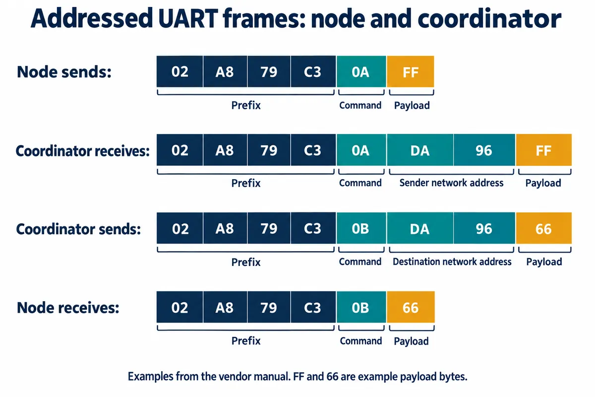
This is the difference between "a button was pressed" and "the button at station B was pressed." Your application still has to map each address to a location or object; the radio does not know what the object means to a visitor. These are the module's UART frames, not the bytes sent over the air.
Sending to one node exposes a second kind of address
The coordinator-to-node test used command 0B with destination 0xFFFF, and coord_to_node arrived. But 0xFFFF is the broadcast destination, so this does not show that only one chosen receiver responded.
We then changed a custom short address, read back the new value (it changed from FFFF to AAFF), and still received messages sent to 0xFFFF. That failure is worth keeping. A successful configuration reply is not the same as a command reaching one particular object.
The vendor manual describes two mechanisms. Command 0B addresses a node by its assigned network short address. Command 0D sets a separate custom short address, used with command 0F. Changing the custom address does not create a new destination for 0B. That points to the next check; it does not prove the failure is fixed.
For a new prototype, keep a record of each module's identity, current network address, custom address if any, and physical location. Then send a harmless message to one receiver while watching another.
The three-module test used custom addressing
For the final test, two routers sat on the controller and a coordinator connected to a USB-to-TTL adapter. We read the coordinator's network settings in a serial terminal (9600 baud, 8N1) and passed the PAN ID and channel to the router code. The routers got custom addresses 0xAAFF and 0xFFAA and exchanged node_to_node with command 0F.
In the vendor format the destination comes before the source, and the driver's argument names are misleading: its source_addr lands in the destination field. Read the frame layout before trusting argument names. Our output showed destination aaff and source ffaa, consistent with that order. It also showed a malformed settings line built from "No response from UART": the messages are good evidence, but the setup log was not a clean initialization.
For your own trial, make the log deliberate: query each role, read each network setting, record each address, send a numbered message, and record the receiver's response. Then you can tell failure to join from failure to receive from failure to act.
Check the joined state properly
Our code waited until a status read returned anything other than None. That is not enough: the vendor firmware also returns valid codes for "not joined" and "still starting." This check interprets a complete status reply against the expected role:
def status_matches_role(frame, role):
    ready_codes = {"coordinator": 0x09, "router": 0x07, "end_device": 0x06}
    if role not in ready_codes:
        raise ValueError("unknown role")
    if len(frame) != 6 or frame[:5] != bytes.fromhex("02 A8 79 C3 01"):
        raise ValueError("not a complete status reply")
    if frame[5] not in (0x02, 0x06, 0x07, 0x08, 0x09):
        raise ValueError("unknown status code")
    return frame[5] == ready_codes[role]
A real serial implementation must also gather partial arrivals, separate command replies from application messages, and time out. "Not joined" should become a recoverable setup error, not an endless loop.
Move the test into the objects people will use
Once destination handling works on the bench, put the nodes in their intended housings. Keep clearance around the PCB antenna and test with the actual enclosure. Give every test message a sequence number and have the receiver acknowledge that it applied the requested state; a transport acknowledgment cannot show that a lamp changed. Log missed messages, duplicates and restart behavior, and include an extended run and a recovery test before anyone else uses the prototype.
The next milestone is modest: one intended receiver responds, a second stays unchanged, and both return to a known state after a restart. Once that is repeatable, you can decide whether to extend this independent network or build compatibility with a particular hub.