
An interactive prop should respond when a visitor brings it near an exhibit. A game controller might change a light as two objects move apart. A robot concept may need to follow a person carrying a tag. All three ideas can lead a team to UWB, but they do not ask the radio for the same information.
Start by deciding what the product must know. A distance trigger needs a dependable answer to "is this object close enough?" A moving dot on a floor plan needs coordinates. A following robot also needs a way to decide which direction to move. On our bench we took on the first question: two Ebyte EWM550 UWB modules on GraftSense carriers, both wired to one Raspberry Pi Pico running MicroPython, configured as a base and a tag and reporting their separation.
Make the first interaction smaller than the final idea
For a proximity-based exhibit, define one observable action: when the tag enters a chosen range, acknowledge it with a light; when it leaves, return to idle. Test that behavior with the intended object, its case and the way a visitor will hold it. A stable interaction at this stage tells you more than a floor-plan animation built on untested readings.
The jump from one pair to a larger system is real work. In a March 2026 Arduino discussion, a builder had individual tag-anchor links working but hit errors when combining anchors, and later reported progress with two tags. That is a useful development lesson, not evidence that the EWM550 firmware supports the same network.
With one range measurement, many positions remain possible: on a flat plane, every point on a circle around the anchor is the same distance away. Direction or coordinates need more information and a supported way of combining it. Do not add a steering arrow to the first demo just because a distance value is available.
The two-module bench setup
One module became the base, or initiator; the other became the tag, or responder. Both were connected to the same controller for this bench test, so it says nothing yet about a self-contained, battery-powered tag or a deployed room network.
The base used UART1 on GP8 (TX) and GP9 (RX). The tag used UART0 on GP16 (TX) and GP17 (RX). Both links ran at 921600 baud, eight data bits, no parity and one stop bit.
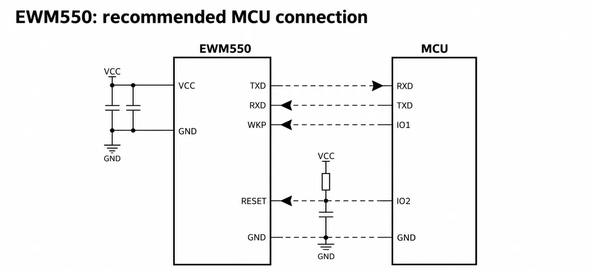
The manufacturer's chip-level connection crosses TXD to RXD. The carrier we used labels its connector from the host side (MTX, MRX), so follow the carrier routing instead of crossing the labels a second time. Also keep the carrier's 5 V input separate from the module's 3.3 V circuitry; on this carrier a linear regulator makes the 3.3 V rail. A convenient connector does not make every exposed pin 5 V tolerant.
Our program entered AT mode, checked communication, set roles and addresses, then reset each module. The pair was configured as:
| Setting | Base | Tag |
|---|---|---|
| Role | 1 (initiator) |
0 (responder) |
| Own address | 0000 |
1111 |
| Destination field | 11110000000000000000 |
00000000000000000000 |
| Controller port | UART1, GP8/GP9 | UART0, GP16/GP17 |
The destination field has five four-character address slots. In tag mode, the documented firmware uses the first slot for the base address. Both sides also need matching radio settings. Record the detected firmware version and channel with the setup instead of assuming two modules have matching saved configurations.
Three nearby buttons on the carrier have different jobs. WAKE wakes the module, RST resets it, and the button labeled RESET is wired to IO2 to restore factory settings. That last one can undo the pairing you just configured. An enclosure for users should not expose a factory-restore button as if it were the everyday power control.
What the terminal actually proves
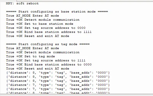
The log shows successful configuration responses and repeated parsed tag reports with distance values of 7 and 8. The documented serial format uses centimeters. We had no reference ruler or measured antenna-to-antenna separation, so those numbers show that ranging is reported, not that it is accurate to a centimeter.
The manufacturer's tag-output example looks like this:
P,1111,10cm
P marks a tag report, 1111 identifies the base in that example, and 10cm is the reported range. Base-side reports also identify the tag and include an SNR field.
The parser in our driver handled one complete report at a time. In a desktop replay, it accepted a complete line but returned nothing when two lines arrived together or when a line was split between reads. A real UART stream can do either. Before adding the proximity interaction, buffer incoming bytes into complete lines, process every line, and track when the last acceptable result arrived. That replay checked software only; we did not rerun the radio for it.
Give the distance trigger some breathing room
A single threshold can make the output flicker when readings move back and forth across it. Use separate enter and leave distances, and choose the gap between them from measurements in the actual setup. You can also require a short run of acceptable readings before changing state. These are rules to build and test, not behavior our code already had.
Treat loss of data as a state of its own. If the visitor turns away or the tag stops reporting, the display should not keep presenting the last distance as current. Choose a timeout and show that the link was lost; never turn missing data into zero distance.
The manufacturer's notes recommend clean supply, good grounding, suitable antenna orientation and clearance from obstacles when readings fluctuate. For your product, test the obstacles that will actually be there: a hand around the prop, a body between devices, the battery, nearby metal and the final case. Record missing updates as well as the values that arrived. A smooth average can hide the moment the interaction stops working.
Decide whether you need a different system
The documented EWM550 arrangement supports a base ranging to up to five tags. That does not mean a tag can combine several bases into an indoor coordinate. Tag-to-tag ranging is not part of the mode we tested, and the tag's destination binding is specific to one base.
An indoor-positioning design has to establish anchor locations, a supported ranging schedule and the position calculation. Other ecosystems split those pieces differently: Qorvo's explanation of its DWM1001 system describes tags ranging to selected anchors, calculating position and reporting it to a gateway. That is an architecture to understand, not a feature list to assign to the EWM550.
For a following robot, separate range from direction and from obstacle awareness. A good near/far demonstration can justify further work on sensing and control; it does not show that the machine can choose a safe path. If your application only needs an exhibit to react to an approaching token, that extra complexity may not be needed at all.
Keep programming access and recovery controls reachable during integration, and check the programming header's supply pin against your programmer before connecting it. Finally, treat published accuracy claims with care: the material we had quoted both ±10 cm and ±30 cm, plus 130 m of range in clear, open conditions. None of those replaces a test in your space. The next useful result is a repeatable record of whether the chosen interaction works at the intended distance, orientation and update rate.