
You have a prototype that responds when someone brings a hand close to it. Now you want a finished front panel: no exposed circuit board, no hole collecting dust, nothing a visitor can poke. Can the distance sensor sit behind a small window and keep working?
It can be a workable design, but the window becomes part of the sensing system. A clear-looking panel can reflect infrared light back into the receiver or weaken the light returning from a hand. The useful next step is to compare the same sensor with and without your intended window before committing to the enclosure.
On our bench we ran a GraftSense VL53L0X time-of-flight module on a GraftPort-RP2040 board with a short MicroPython program and recorded the distance readings. That showed an exposed sensor responding to a moving hand. This note follows that baseline, then uses it to plan what an enclosed interactive prototype still has to prove.
Decide what the user should experience
For a tabletop exhibit, the requirement might be "start the animation when a hand enters the interaction area." For a small display, it might be "wake before someone reaches for the controls." Write down the closest and farthest positions that should count, the approach direction, and what should happen when the reading is uncertain. A visitor should not have to find one exact sweet spot, and an invalid reading should not make the interface flash on and off.
This enclosure question has a history. In a February 2021 Arduino discussion, a builder wanted glass and a silicone seal over this sensor and was unsure how to calibrate it. That describes the integration problem well.
What is on the little board?
The VL53L0X emits invisible infrared light and uses the returning signal to estimate distance. The module does that measurement internally, so the host reads a number over I2C instead of timing a light pulse itself. The board brings out power, ground, SDA and SCL on a four-pin connector. The emitter and receiver still need an unobstructed optical path, and a case wall, decorative border or misplaced gasket can become part of what the sensor sees.
ST's datasheet describes ranging up to 2 m, with performance tables tied to specific target and lighting conditions. That is a component capability, not a promise that a dark sleeve behind your panel will be detected accurately at two meters.
Reproduce the exposed-sensor baseline first
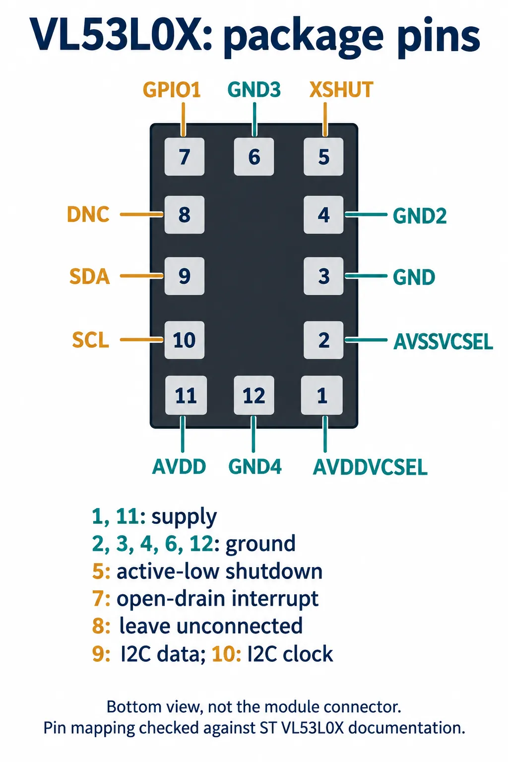
Our setup used SDA on GP4, SCL on GP5 and a 100 kHz I2C bus. Identify the module's actual connector labels before wiring; a chip pin diagram and a four-pin module connector describe different things.
The module includes a regulator and bus pull-ups, but that does not make every voltage on its input connector safe for a controller pin. Check the fitted regulator and measure the rail before relying on a stated logic voltage.
If you design a PCB around the bare chip, take the pin mapping from ST's package drawing rather than from a secondhand pin table.
Next, check the I2C address. MicroPython expects the seven-bit address, 0x29. ST's diagrams show 0x52, which includes the write bit; both describe the same default address. When several modules share a bus, do not pick whatever device falls inside a broad scan range.
from machine import I2C, Pin

i2c = I2C(0, sda=Pin(4), scl=Pin(5), freq=100_000)
addresses = i2c.scan()
print([hex(address) for address in addresses])
if 0x29 not in addresses:
    raise RuntimeError("VL53L0X not found at its default address")
That check confirms the expected address without starting a measurement. Keep the driver version with the experiment: the same class name in another library does not guarantee the same initialization, timing or calibration behavior.
Follow the measurement, not just the printed number
Our program started continuous ranging, read a distance in millimeters, printed it if it fell between 0 and 2000, and waited 0.8 seconds before the next read. No ranging period was passed, so the driver used its default continuous mode.
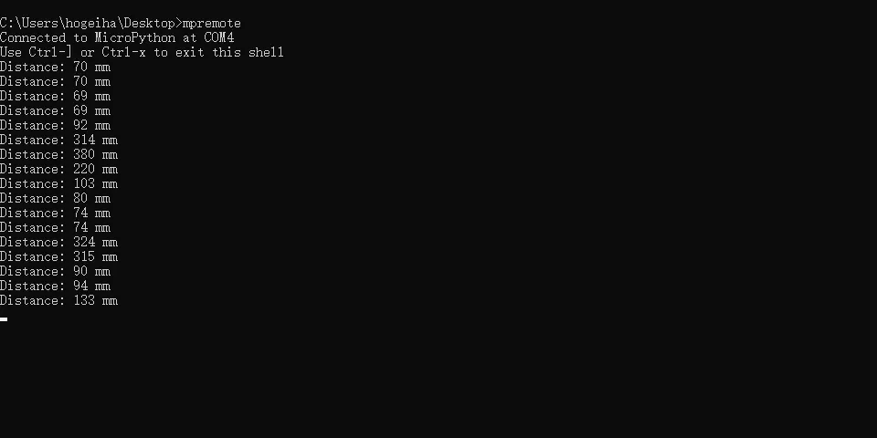
The readings changed as a hand moved toward and away from the sensor. They are reported distances, not checked against a ruler, and there was no window in this test.
Before readings trigger an interaction, the software has to tell a valid range from an unsuccessful measurement. Check whether your driver's read path interprets the full ranging status or only returns a distance; accepting every number between zero and 2000 is not a substitute. Use an implementation that exposes status as well as distance, then decide how the interface behaves when the sensor has no trustworthy answer. Also settle on one known software version first; otherwise a software change and a new window can produce two causes for the same symptom.
Add the window as a separate experiment
Fix the sensor in place with a target at measured positions. Record the exposed readings and the unsuccessful measurements. Then insert the intended window without moving the sensor or the target. This comparison isolates the effect of the new optical surface.
Some light can return from the window itself instead of the target. ST calls this optical crosstalk, and it depends on the material and the gap above the sensor. ST's cover-window guidance favors a thin, highly transmissive window close to the sensor and discusses a gasket where the mechanical design needs more separation. Those are starting points, not universal dimensions.
Do not choose a material by visible transparency. Ask for its transmission around the sensor's 940 nm wavelength, then test the actual part, including tint, surface finish and any decorative coating. The opening must keep the light paths clear across assembly tolerances.
Calibration comes after a sensible optical arrangement. A June 2021 ST support answer explains why a crosstalk calibration taken too close to the target can fail to reveal enough crosstalk. Calibrate with the final window, spacing and mounting in place, following ST's procedure, and save the result with the hardware revision. A new window material or a changed recess deserves another check, even if the panel looks the same.
Test the interaction people will actually use
Once the windowed sensor gives repeatable readings, test with what your audience will bring near it: hands at different angles, sleeves, light and dark objects, and the background behind them, under the lighting where the prototype will be shown. Then work through these questions:
- Does the window change the reading? Compare the same target positions with and without it to decide whether optics or calibration need work.
- Does a dark sleeve still trigger it? Try intended objects and approach angles to set a realistic interaction area.
- Does a fingerprint cause false activation? Compare clean and handled windows to choose the surface and the acceptable behavior.
- Does reassembly change performance? Remount the sensor several times with the intended fixing method.
- What happens when no valid range is available? Check status and interface behavior together so the fallback is calm rather than flickering.
For a simple wake-up interaction, consider a nearer activation boundary and a farther release boundary so small variations do not toggle the display, and require several valid readings before changing state. Set those rules from measured behavior, not from our exposed-sensor test.
A successful result is a defined interaction area that survives the real front panel, ordinary handling and reassembly. It does not need to reach the largest number on the datasheet. Paired readings with and without the panel, the window material and a sketch of the sensor position are what an integration review needs to work from.