
You have a working interaction, such as a button, a visitor sensor or a message from an app, and you want it to produce a small burst of mist. For a design installation or a physical experience prototype, the hard part is getting the same response every time, with water delivered to the mist head and kept away from the electronics.
On our bench we switched a wetted ultrasonic mist head from a MicroPython controller through a GraftSense FM8118 mist module. That demonstrates the control idea. It does not establish a measured mist rate, enclosure performance or dependable unattended operation.
Choose the effect before choosing the control method
Mist is already being used as an interactive output. The July 2026 Teardown program listed a workshop on programmable mist as a creative medium, using a different open-source mist-maker board. That is a relevant example for artists and designers, not evidence that every small mist module offers the same features.
Describe the effect in terms someone can observe: start after a trigger, stay visible for a chosen interval, then stop. A gentle continuous haze and an occasional puff are different requirements. Avoid starting with "variable intensity" unless you know how the driver exposes that control.
This comes up in real projects. A March 2021 Arduino discussion about varying mist intensity moved between high-frequency transducer drive and slow on/off switching, which are different operations. The driver we used implements switching commands, not a verified continuous mist-level control.
Keep the mist driver and the interaction controller separate
The FM8118 handles the mist drive. Its documentation describes a nominal 108 kHz, 40% duty-cycle drive signal; the board's power stage and matched piezo disc do the physical work. Your MicroPython program does not generate that ultrasonic waveform by calling on() repeatedly.
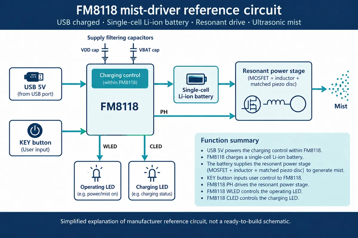
The controller operates the module's control input, and the chip also manages charging and indicators. That division lets the application decide when the effect should happen while the driver circuit runs the mist head.
Watch the board labels. The controller connects to the interface labeled DOUT, which reaches the chip's KEY input. The piezo disc connects to OUT. They are different connections: the mist head must never go on a microcontroller signal pin, and DOUT is not a sensor that reports how much mist is coming out. The FM8118's package drawing also had pin-label errors; we followed its pin table and the module schematic (KEY pin 3, GND pin 4, PH pin 5, WLED pin 6). Verify against the actual part before wiring.
The bench setup
We used a GraftPort-RP2040 controller, a four-wire HY2.0 cable to its DIO0 connector, the mist module, a single-cell battery and a mist head fed by a cotton wick. GPIO6 was the control line; the other signal position was unused. Check that routing on your own controller and cable.
The battery went to BAT and the mist head to OUT. In our setup the module did not run normally from its Type-C connection alone; it needed the battery, even though some module documentation suggests broader USB operation. We have not resolved that, so reproduce the battery arrangement before investigating other power configurations.
The wick has to be wetted before the test. It supplies water to the small mist head and is part of the working assembly, not packaging.
Keep the assembly open for observation at this stage. Check the water path, the direction of the mist and where droplets collect. For an enclosure, separate the wet assembly physically from the electronics, and keep the wick and reservoir reachable for service. Our open bench setup does not show that an enclosed version handles water well.
Understand what the program's status means
We used our team's FM8118 driver for MicroPython. The test called on, off and toggle, waiting ten seconds after each, and printed the state the driver reported.
Reading the driver explains an important limitation: the reported state is an internal Boolean set by the program. It does not read a flow sensor, check for water or confirm that the head is vibrating. A printed True means software recorded an on command; a dry wick or another hardware fault could still mean no visible mist.
The driver also treats stopping as a sequence, because the chip's button input is edge-sensitive:
| Application call | What the driver does | What it establishes |
|---|---|---|
| Initialize | Set GPIO high; store "off" | Software starts in an off state |
| On | Set GPIO low; store "on" | An on command was issued |
| Off | High, wait 100 ms, low, wait 100 ms, high; store "off" | The stop sequence was issued |
| Toggle | Choose on or off from the stored state | A software-requested change |
| Status | Return the stored state | No direct confirmation of mist |
So this is not interchangeable with a generic output that simply follows a high or low level. For an installation, test what happens after a controller reset, a module power interruption or a low-battery shutdown, where software and hardware can disagree about the current state. Also test how the effect stops when the application exits: our test's keyboard-interrupt handler printed a message without explicitly switching the mist off.
Watch the physical result, not only the terminal
The mist head produced visible mist on the bench. That is evidence of a working control path in that setup, not a measurement of delivered water volume.
For a first interaction test, record whether mist starts after the command, how long it takes to become visible, and whether it stops after the intended sequence. Repeat with the head mounted where you plan to use it. Check the wick after pauses and refilling, and watch for droplets reaching connectors or surfaces visitors will touch.
If you need a precise dose or a guaranteed room-humidity change, this test does not answer that. We have no measured mist rate, droplet distribution or humidity data. Keep the claim at the level of the evidence: software-triggered mist in a bench prototype.
Move toward an enclosure with a small set of checks
The chip documentation warns that switching activity in the driver can disturb battery-voltage detection and recommends local supply filtering.
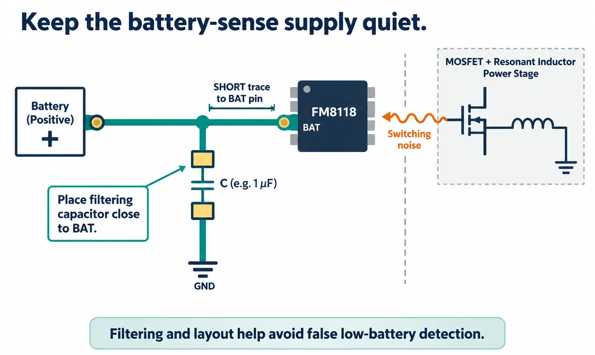
Keep that part of the circuit when moving from a module to a custom board. The module's shared ground also means separate power connections should not be mistaken for electrical isolation.
Before making several units, test the complete assembly through repeated starts, stops, refills and power interruptions. Confirm the battery and charging arrangement, the actual shutdown behavior and access to the wet parts. The chip's nominal timeout and charge-current figures are component data; they do not establish battery runtime or product reliability.
Then decide whether the module suits a short supervised demonstration, whether the control needs feedback, or whether you need a different driver with documented mist-level control. Those decisions are easier once one observable interaction works consistently in its intended physical arrangement.