
You have a working board, and the next idea sounds simple: let someone control it from their phone. Perhaps it is a light for an installation, a button-operated accessory or a sensor whose readings need to appear on screen. Before commissioning a polished app, make one small interaction work all the way through: the phone sends a request, the controller receives it, and the phone gets a useful response.
This is a common transition for software people new to hardware. A September 2026 Reddit discussion about a Bluetooth keyfob prototype describes it: the founder could handle the software but needed help with the electronics and enclosure. The app, the board and the case need a shared definition of what the first prototype must do.
On our bench we tried two Bluetooth Low Energy modules, an Ebyte E104-BT02 and an HC08, each wired to a Raspberry Pi Pico running MicroPython and driven from phone debugging tools. Both exchanged short text with the phone. The most useful lesson was visible in the results: a wireless connection can be working while the application still has to decide where a message begins, where it ends and what it means.
Start with one interaction you can recognize
For a light controller, a suitable first test might be "send a brightness setting and receive the setting the board accepted." For a sensor, "request one reading and receive its value and status." Our tests started one step earlier, by sending and returning recognizable text.
A general-purpose BLE tool is enough for that step. Nordic's nRF Connect for Mobile can discover services and characteristics, write values and enable notifications. We used other phone tools for these tests.
In BLE, a service groups related functions, and a characteristic is an addressable value or endpoint within that service. You do not need a complete app to inspect them, but you do need to know which endpoint accepts a request and which one returns information.
First establish the wired half of the connection
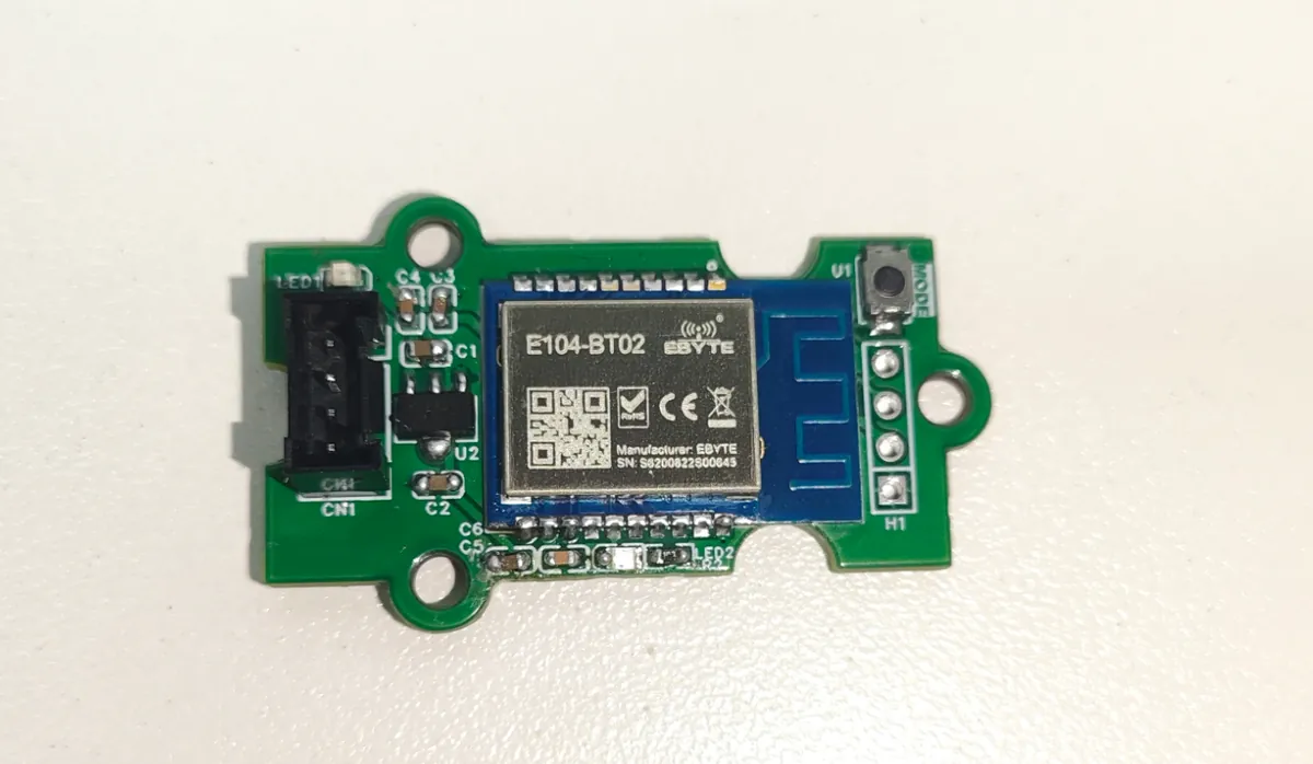
The E104-BT02 carrier supplies the module through a 3.3 V regulator from the 5 V input, so the carrier input and the module supply are different points. The UART is the short wired link between the controller and the module; BLE carries the other half of the journey to the phone.
We used UART0 with GP16 for controller transmit and GP17 for receive, at 19,200 baud. The carrier labels MTX and MRX from the host's side: MTX feeds the module's receive input and MRX brings the module's output back. On the carrier drawing, CN1 pins 1 to 4 are ground, 5 V, MTX and MRX; the wake pin P06 is on the separate H1 header. Check the assembled revision before wiring.
Configure the module, then give the UART back to your data
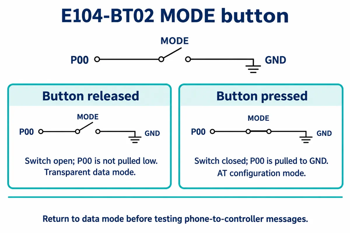
Pressing MODE pulls P00 low and selects AT configuration; releasing it returns the module to transparent data mode, where serial bytes pass through the Bluetooth link. Our program kept the stages separate. It queried baud rate, name, connection state, transfer setting, role and address, then gave the operator 15 seconds to release MODE and connect the phone. That countdown was our convenience, not a manufacturer requirement.
The console reported 19,200 baud, a peripheral role printed as SLAVER, an initially disconnected state and an mtu setting of 100. The name E104-BT02-V5.0 is a device name, not proof of a Bluetooth specification version.
One detail to settle before reproducing this: P06 controls wake and sleep. The manufacturer pin table says a falling edge wakes and a rising edge sleeps. Use documentation matched to your firmware and confirm the resulting state rather than assuming it.
On the phone, choose a direction for each message
The E104 manufacturer instructions describe service FFF0, with FFF1 for notifications from the module, FFF2 for writes from the phone and FFF3 for configuration. Enable notifications on FFF1 so incoming data appears on the phone, and write to FFF2 to send toward the controller. A connection alone does not mean the phone is listening on the return path.
This is why "Bluetooth connected" is too little for an app specification. Record the service, the write endpoint, the notification endpoint and their supported properties on the actual firmware, instead of assuming every module exposes the same interface.
Watch what arrives, not just what you sent
After configuration, the E104 program sent Hello from RP2040 and echoed whatever the controller read, printing each read and its byte count. The phone sent the 21-byte text hello-104-from-iPhone. The controller received it in separate reads: one exchange showed 9 bytes then 12, another 7 then 14. One user-entered string does not have to arrive as one read.
We cannot tell from the recording which layer caused each split. The manufacturer's default 20-byte transfer limit, the module's configured transfer setting and the program's UART reads are related but different things. Raising a setting named MTU does not make each command arrive as one object.
Agree on a small message format before building the screen. A line ending can delimit a short text command; a length field can delimit a binary one. Either way, the receiver has to accumulate incomplete input and act only on complete messages. If a command changes a setting, return the accepted setting or a clear error. A plain echo loop is only the starting point.
Repeat the round trip with a second module
The HC08 reached the same milestone with a different module and driver, again on UART0 GP16/GP17, this time at 9,600 baud. The console identified HC-08, firmware HC-08V10.8 dated December 2021, and a Slave role, then printed the incoming test string. The controller replied with a get data prefix and the received bytes, and the phone showed the round trip. That shows a visible exchange for one small test, not arbitrary commands, multiple phones or every reconnect case.
The HC08 carrier is one particular design, not any board sold under that name. An older reference circuit used an RS-232 interface; our V1.1 carrier uses a different UART interface circuit. Do not mix their connector descriptions or assume a bare module accepts a breakout board's voltage. The HC08 driver's calls differ from the E104 code, so reuse the logic (query, connect, send, observe, respond), not the drivers or the E104 UUIDs.
Turn the successful exchange into an app brief
Once one useful interaction works reliably, ask someone unfamiliar with the bench setup to try it. They should be able to find the right device, request an action and tell whether it happened. A debugging app helps the engineer; it is not evidence that a customer can use the product.
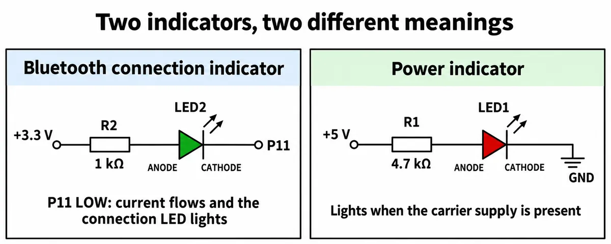
There are three states to explain: the board has power, the phone is connected, and the device has acted on a request. The E104 carrier has separate power and connection indicators, but neither says a setting was accepted or a reading is current. That belongs in the response your application defines.
Before adding screens, record:
- the device identity and the service and characteristic properties seen on the actual firmware;
- the bytes sent, the reconstructed request and the controller's interpretation;
- the returned value or error, not only a local write success;
- what the user sees after a disconnect, a power cycle and a reconnect;
- results on the target phones, in the proposed enclosure, with the intended power arrangement.
The last item is still open. We have no battery-life measurement, security review, cross-platform app test or production evidence from these tests. What we demonstrated is a phone-to-controller text exchange, and what the next interaction needs.