
Your wired sensor prototype is working, but you want a different Ethernet board. Perhaps the next version needs a different network feature, or you want to move from an RP2040 board to an RP2350 board. Keeping the existing carrier, cables and sensors would save rebuilding the whole setup, and matching rows of pins make that look straightforward.
The question is what those pins already do. In a June 2024 Arduino Forum discussion, a developer adding sensor communication to an existing WIZnet and Pico project had only a few pins left and wanted to keep the serial debugging connection. That is the practical problem with an upgrade: the new function has to coexist with the functions you already use.
We use the GraftPort-Pico-ETH carrier on our bench, with its connector assignments and an SD-card and serial-port test we ran on it. Comparing that carrier with the WIZnet board documentation turns up two connections that need attention before a W6300-EVB-Pico2 swap. The carrier may still be useful, but the assembly has to be checked as a whole.
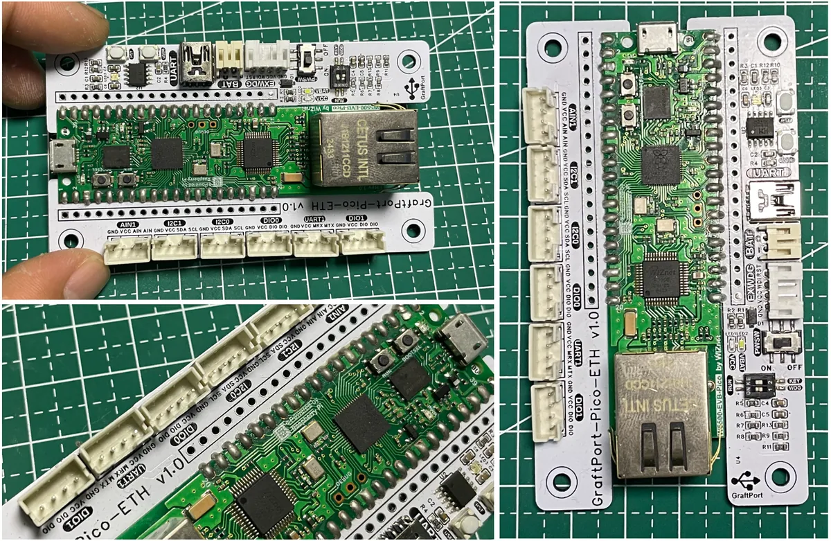
Start with the parts you want to keep
A carrier is the larger board underneath the development board. This one brings connections out to separate sockets: sensors, a serial interface, external power, an external watchdog and a microSD card. That makes a bench prototype easier to assemble than a collection of loose jumper wires.
The reset button, user button and reset-source selector have different jobs. The user button is connected to GP26 for application input. The selector chooses between the carrier's reset-button path and its external-watchdog reset path. Moving that switch changes how the assembly resets; it does not reassign any GPIO connection. The BAT connector is an external-power connection, not evidence of a built-in battery charger.
Make a short list of what your application actually needs from the carrier. An I2C sensor, an SD card and a serial console use a different set of connections from a system that also needs both digital ports and the external watchdog. That list decides whether a board swap is a small software change or a hardware change.
Two carrier connections that change meaning
The W5500-EVB-Pico2 pin table assigns GP16 to GP21 to its Ethernet controller. The W6300-EVB-Pico2 documentation instead reserves GP15 to GP22 for Ethernet. Both sets of assignments are already wired inside the respective development boards.
For this carrier, the two extra pins matter:
| Connection on the carrier | Assignment on W6300-EVB-Pico2 | What to resolve before using both |
|---|---|---|
| GP15 is brought out at the second digital connector | Ethernet interrupt, INTn | A connected digital peripheral must not treat this as a spare GPIO. |
| GP22 goes to the external watchdog's WDI connection | Ethernet reset, RSTn | A watchdog-feed signal cannot be assumed independent of the Ethernet reset line. |
This comparison identifies overlapping uses in the documentation. It is not the result of a swap tested on our bench. Whether either connection causes a problem in your assembly depends on what is connected, how the software configures it and the exact board revisions. Leaving a socket empty does not make the Ethernet signal disappear; it only means there may be no external circuit competing with it.
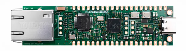
Do not carry the W5500 initialization settings across unchanged either. On the W6300 board, the controller's chip-select and clock assignments differ as well. Start from the firmware and example for the exact replacement board, then reconcile that example with the peripherals you intend to keep.
The useful question is specific: can this board support our sensor, storage, control and recovery connections together? A shared header layout answers only part of it. You do not need to redesign everything, but you do need a pin allocation that describes the complete assembly.
Use a simple carrier test as a starting point
Our first check on the carrier was manageable: write a known file to the microSD card and exercise the USB-to-UART path. It does not depend on a live server or sensor reading, so those variables do not obscure the basic carrier test.
The SD socket is on the underside of the carrier. Keep access to it in mind before fixing the assembly inside an enclosure.
The test program creates SPI1 with clock on GP10, transmit on GP11 and receive on GP12, and selects the card with GP13:
spi = SPI(1, baudrate=1320000, polarity=0, phase=0,
          sck=Pin(10), mosi=Pin(11), miso=Pin(12))
sdcard = SDCard(spi, cs=Pin(13))
A comment in our file said GP9, but the executable line and the carrier mapping use GP13. That is the assignment to verify against your board. These four storage pins are separate from the Ethernet assignments compared above, so a passing SD test does not validate the rest of a replacement-board configuration.
The test program formats the card before mounting it. Its vfs.VfsFat.mkfs(block_device) call can erase existing data. Use a disposable card for that test. A logger meant to preserve recordings needs a different startup policy, with formatting kept separate from normal operation.
Follow the upload and the result
We compiled the supporting modules with mpy-cross and transferred them with mpremote; main.py went across as source. Use firmware and compiled modules that match the actual board and MicroPython version. A UF2 file that worked on one board is not a universal image for every Pico-shaped board.
One run first reported a serial error and "no device found," then connected to MicroPython on the next attempt and listed the uploaded files. We did not record what changed between the attempts, so treat that as an open question rather than a fix. Port numbers belong to the computer, not the board.
After mounting the card, the program writes /sdcard/embedded_websites.csv, a fixed list of website names and addresses embedded in the program. Opening it in a spreadsheet confirmed the write. It is a file-writing check, not data downloaded over Ethernet or collected from sensors.
The same program configures UART0 at 115200 baud on GP0 and GP1 and exchanges text with a PC terminal. That tests another carrier connection independently of the Ethernet controller, which is useful when checking that a new assembly still supports the existing peripheral paths. The program stops its receive loop after ten passes and then blinks the LED; that is its programmed end state, not a deployed logger's behavior.
Make the replacement pass the complete application test
Once the individual connections work, test them together on the replacement board: Ethernet traffic while writing to the card, the actual sensors and controls connected, and the intended reset or recovery arrangement enabled. Use one documented configuration rather than a mixture of pin assignments from different examples.
For the two overlapping connections, decide whether to change the peripheral connection, revise the carrier or choose a different core board. Record that decision alongside the firmware target and carrier revision. A working SD-card test cannot clear a conflict on the watchdog connection, just as an Ethernet link light cannot prove the sensor interface still works.
That produces a meaningful upgrade result: the functions your product needs operate together on the chosen assembly. Our carrier tests give a starting configuration; the pin comparison shows where the proposed swap needs more work. We have not yet run the swap itself on hardware.