
A small OLED can look convincing on the workbench: it lights up, shows a few lines of text and fits beside the development board. Put it behind a window in a handheld device or on the front of a desktop instrument, and you may find that the number users need is too small to read comfortably.
If you are choosing a display for a working hardware prototype, test the screen layout and its physical position together. Diagonal size, pixel count and controller name each tell you something different, and none of them alone tells you whether someone can understand the display while using the product.
On our bench we ran two GraftSense OLED modules from a GraftPort-RP2040 carrier in MicroPython: a square, grayscale SSD1327 panel and a narrow, monochrome SH1107 panel. This note uses those runs as the starting point for a more useful enclosure test.
Begin with the information someone needs to see
Before comparing display modules, write down the most important thing a user must recognize. For a small instrument, that might be one reading with its unit and a clear sign that the measurement is ready. For an interactive controller, it might be the selected mode and the value being changed.
This shows up in real projects. In an April 2020 Seeed forum discussion, an environmental-sensor builder had already mounted an OLED in the enclosure lid and found the text too small. They wanted a larger display and a connector that sat under the board. The problem crossed software, screen choice and packaging; another demo animation would not have fixed it.
The two modules offer different spaces for that information:
- SSD1327 square OLED: 128 × 128 pixels with 16 gray levels per pixel. More vertical room, useful for a reading with a small graphic or several separated elements.
- SH1107 narrow OLED: a 64 × 128 panel used horizontally as 128 × 64. A shallow strip, useful for a compact status line when the main information is short. Its contrast setting changes intensity; it does not make a one-bit image grayscale.
Some of our module documentation described the narrow panel as 128 × 128, but the panel drawing, board marking and code dimensions identify the narrow screen. Plan from the actual panel and matching driver settings.
Size the enclosure opening from the drawing, not the diagonal
The lit area is smaller than the glass, and the glass is smaller than the full assembly with its carrier, cable and connector.
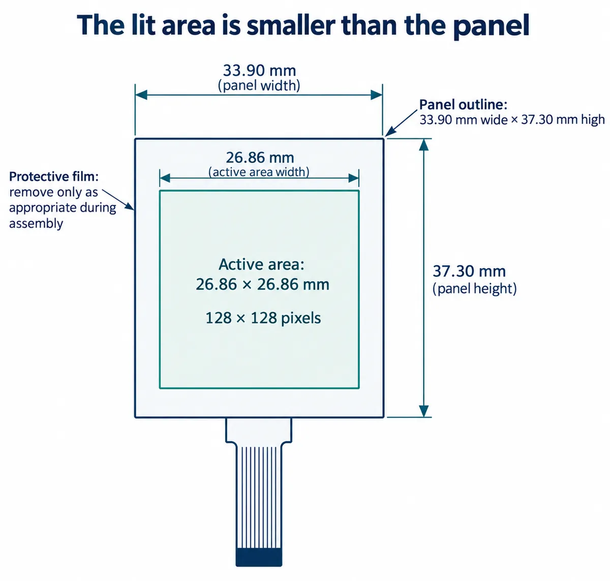
For the narrow panel, the active area is 29.42 × 14.7 mm in landscape. Its drawing separately marks the visible area, panel outline and flexible connection. Those boundaries matter when a bezel, adhesive or printed enclosure lip sits in front of the display.
Make a simple front-panel mock-up before committing the enclosure. Put the real display behind an opening, include the intended cover material, and look from the distance and angle at which the product will be used. Check the connector and cable bend at the same time: a screen can fit the window while its cable keeps the board from sitting where you expected.
Reproduce one clear screen before running the whole demo
Both modules connected with SDA on GPIO4 and SCL on GPIO5. The square-screen program used software I2C at 100 kHz; the narrow-screen program used hardware I2C0 at 400 kHz. Those are our recorded configurations, not a promise that every replacement module works with either.
Each controller needs its own driver, and an I2C scan can find a device without telling you which one. Both programs looked for 0x3C or 0x3D and found 0x3C. Some SSD1327 documentation lists 0x78 and 0x7A; those are address bytes including the write bit, not the seven-bit addresses MicroPython uses. The drivers we ran carry MIT licenses and credit open-source work by mcauser (micropython-ssd1327) and peter-l5 (SH1107). Our installation notes named version 1.0.0 while the archives we ran were 1.0.1, so keep the exact driver version with your test notes.
The square-screen demo stepped through text in four gray levels, dots and lines, contrast changes, inversion and rotation. It also showed why stage labels are not enough: the stage announced as "Rectangles" printed that word, but its code drew no rectangle. Look at the screen, not just the terminal messages.
For a product experiment, replace the demo strings with the longest label, unit and error message you actually expect. Start with one screen that communicates those well. Add scrolling, inversion or rotation only when they solve a specific interaction problem.
Check the narrow screen at its real size
The SH1107 run showed useful display activity, but also crowded text and trails while scrolling. One cause is visible in the code: two text rows started at y=40 and y=45, five pixels apart. The standard MicroPython framebuffer font is eight pixels high, and the driver's normal text method uses it, so those rows overlap. A first fix is to separate the lines and shorten the last label:
oled.fill(0)
oled.text("SH1107 Demo", 10, 4, 1)
oled.text("128x64 OLED", 10, 18, 1)
oled.text("MicroPython", 10, 32, 1)
oled.text("I2C 400kHz", 10, 46, 1)
oled.show()
This is a proposed layout change; we have not rerun it on the hardware. Spacing prevents collisions but does not make letters larger. If the key reading is still hard to see, show less, use a larger-font implementation or choose a larger display, and judge it on the real panel. Enlarging a screenshot on a laptop hides the problem.
Our terminal capture also still printed an older "128x128" startup label while the code specified 128 × 64. When you record a test, include the panel identifier, driver version, dimensions and orientation so someone else can reproduce the same screen.
Treat brightness and power as part of the assembled product
The demos changed contrast, inverted the screen and turned the display off. Those are useful controls, but they do not establish battery life. The carrier also has power circuitry and an indicator LED, so a chip or panel sleep-current figure is not a measurement of the whole connected module.
The panel's reference circuit separates the logic supply from a higher panel-drive supply and recommends switching panel power to avoid leakage paths. That is background for understanding the module, not an instruction to apply panel-drive voltage to its four-pin connector; use the carrier's own power design and input requirements.
For a battery prototype, measure the assembled system with the intended image, brightness and update rate, then again with the screen commanded off. For readability, use the intended room lighting and cover window. These two checks help you choose a workable display state without assuming maximum brightness or the smallest screen is the right answer.
The next test is a person reading the installed display
Place the prototype where it will be used and ask someone unfamiliar with the code to find the main reading, its unit and whether the device is ready. Watch whether they lean closer, wait for text to scroll, or mistake a stale value for a current one. Use that to decide what belongs on the first screen and what can move to another view.
Our bench runs cover physical connections, controller-specific drivers and visible drawing operations. Connecting them to the enclosure and to the task someone is trying to complete is the next build; we have not run that user test yet.