
Your board works on the bench. Now it needs a case that people can handle, and the space around the electronics is shrinking. Adding a fan looks like a simple fix. Before you commit to the enclosure, though, there are two separate questions: can you control the fan, and does the assembled device stay cool enough during its intended job?
On our bench we answered part of the first question. We connected a small two-wire fan to a GraftSense MOSFET fan module and changed the commanded PWM duty from a MicroPython program on a GraftPort-Pico controller. The fan ran. The test did not measure temperature reduction, fan speed or noise inside a finished case.
Start with the enclosure problem
For a small instrument or interactive exhibit, cooling competes with other needs: keeping fingers and loose objects away from the blades, leaving room for cables, and avoiding a distracting sound beside the user. A fan opening is part of the enclosure design, not a detail to add once the rest of the case is finished.
A PINE64 builder's June 2021 account shows the distinction. After making a fan mount for an open enclosure, the builder found cooling less effective than expected with the hot chip beneath the fan's center, and later changed the fan orientation and control arrangement. Different board, different fan, same question: where does air actually pass through your assembly?
The fan is nominally 20 × 20 × 6 mm. Those dimensions describe the fan, not the space needed for the module, plug, wire bend and nearby wall. Check all of them in a rough case before finalizing mounting holes. The drawing also gives wire polarity; a matching connector shape does not establish that another fan is wired the same way.
What the module controls
The board switches the fan's power return through an AO3400 N-channel MOSFET. The host provides a control signal, while the fan draws its power from the 5 V supply. A high control level turns the switch on and a low level turns it off. PWM repeats that action, changing the fraction of time the fan is powered.
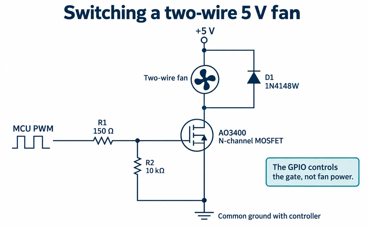
The circuit uses a 150 Ω resistor between the PWM signal and the gate, a 10 kΩ pull-down from gate to ground, and a diode across the fan connection. Those are this board's choices, not a guarantee that any replacement fan will behave correctly. Check the exact fan's permitted control method and look at the switching waveform when you integrate it.
This is a two-wire fan whose power is switched. It is not a four-wire fan with a separate PWM control input, even though our software used 25 kHz PWM. A frequency common in another fan interface does not validate this power-switching arrangement.
Connect the fan at the FANINF connector and the 5 V supply at the POWER terminal, observing polarity. The module's signal connector also carries supply and ground, so check the schematic before connecting two separate power sources. A dedicated power terminal does not mean electrical isolation, and it does not prevent supply disturbances on its own.
The control sequence we ran
We used the DIO0 connector, with GPIO6 going to the module's control pin; GPIO7 was unused. The control pin is labeled DOUT on the board, but it receives the host's signal. Establish a common ground and verify the connector mapping before applying power.
The program used a small fan class from our team's driver library, defaulting to 25,000 Hz. It accepts a command from 0 to 1023, clamps it and converts it to MicroPython's 16-bit duty setting. Its speed query returns the stored command. The module has no tachometer input, so that number is not RPM.
The sequence turned the fan fully on for five seconds, off for five seconds, then stepped through 256, 512, 768 and 1023, holding each for five seconds. The terminal recorded the requested values: 1023, 0, 256, 512, 768 and 1023, which correspond to about 100%, 0%, 25%, 50%, 75% and 100% commanded duty. Half duty does not establish half speed or half airflow, and we recorded no RPM trace, temperature log or sound level.
The fan's supplier lists 5 V, 0.12 A, 13,000 RPM, 0.77 CFM and 26 dBA. Those are reference figures, not results from our test. The sound figure comes from a microphone one meter from the fan in free air; it does not describe your assembled device on a desk.
Turn the bench demo into a useful cooling test
Run the actual workload you expect, with the intended case, cable routing and power supply. Record ambient temperature and the temperature of the parts whose limits matter. Compare a safe baseline with the fan running, keeping the workload and measurement positions the same. A few seconds at each duty, as in our control test, says nothing about the settled temperature of an enclosure.
Air also needs somewhere to enter and leave. Fan makers' installation guidance notes that walls close to a fan tend to reduce airflow and raise noise, with a blocked intake especially harmful. Their suggested clearances depend on the equipment and the fan, so test your installed arrangement rather than treating the free-air rating as the airflow through a crowded case.
Listen to the device where people will use it. Test starting from rest at the intended low setting as well as stepping down from full. Check whether the case or mounting adds a rattle or whine. An August 2011 Arduino discussion began with exactly this: a fan turned but made a high-pitched sound below full duty. That report names a question to test; it does not prove the same behavior for this module.
Keep a suitable guard in the installed design. Removing an obstruction may help airflow, but exposed blades change the product's physical protection. For a sealed or dusty environment, reconsider the cooling approach instead of assuming an open vent is acceptable. Specify the environment first, then choose the case and the fan.