
Your prototype can send readings to a laptop, but the next demonstration needs them on another computer across the room. It might be a test fixture, an interactive installation or a small monitoring device. Replacing the controller just to add a network connection may be unnecessary: a serial-to-Ethernet module can carry the existing serial data across the local network.
The useful question is what happens on either side of that connection. Which computer listens? What address does the device use? When several readings arrive together, how does the receiving program tell them apart? Those decisions matter more than getting the first line of text onto a terminal.
On our bench we connected a TASTEK TAS-LAN-755C serial-to-Ethernet module on a GraftSense carrier to a GraftPort-Pico board running MicroPython, and exchanged data with a PC over TCP, UDP and HTTP.
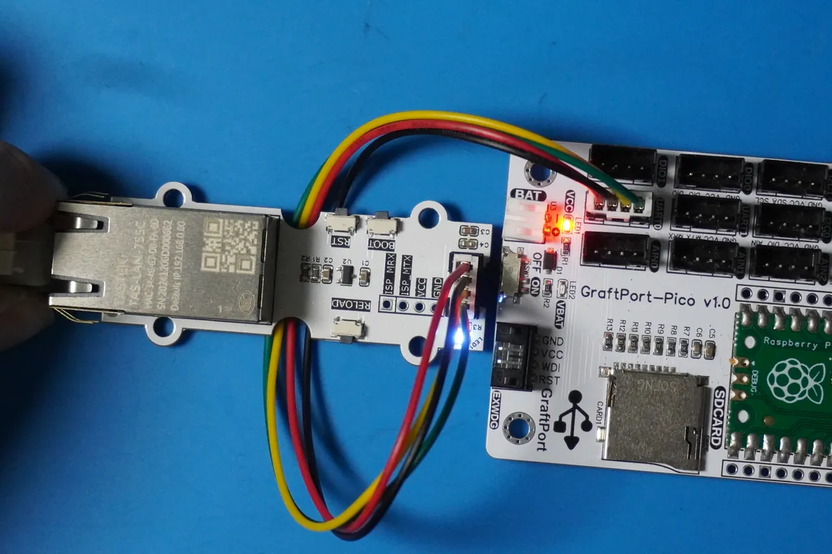
Keep the serial interface, add a network endpoint
The controller sends bytes over UART, a serial interface with separate transmit and receive lines, and the module handles the Ethernet side. In its transparent data modes it forwards data between the two; your application still decides what those bytes mean.
That makes this approach worth considering when the prototype already has a working serial command or measurement format. It does not turn a sensor into a cloud service, translate industrial protocols or deliver a finished remote-control product. Our test covered local communication only.
Start from the carrier connections rather than the bare module pinout.
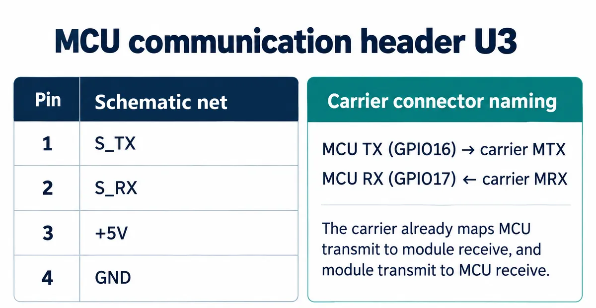
We used controller TX on GPIO16 and RX on GPIO17, with a common ground. Crossing the signals again because both ends say "TX" would undo the carrier's routing. The example ran UART0 at 9,600 baud; match the serial settings at both ends before investigating the network. The module's specification gives a nominal 3.3 V supply, and a header marked +5V is power, not permission to drive the UART signals at 5 V.
The specification also lists 10 Mbps Ethernet for the 755C and 10/100 Mbps for the 755W. Neither figure says how quickly the whole serial application delivers useful measurements; start from the serial rate and the real message size.
Give both ends an address you can explain
On our bench network the PC was at 192.168.2.97 and the module was given a static 192.168.2.251 with a 255.255.255.0 mask. Those are our values; choose available addresses on your own network. The module's web configuration page shows local address, mask, gateway and DNS as separate fields. A static address made our tests repeatable. For a prototype that moves between sites, decide who assigns its address and how the installer will find or change it.
Record the device address, PC address, serial settings and the port each program uses. A port identifies a particular service at an address. In our tests the module used local port 8080 and the PC tool used 9000; those were test choices, not Ethernet defaults.
The driver separates command mode from data mode. It sends the documented +++ sequence to enter command mode, applies settings, saves them and restarts the module before returning to data transfer. Check the returned result rather than assuming a short delay means success. Our driver is demonstration code, and its command-entry path still needs a defined timeout outcome before unattended use.
Choose who starts the TCP connection
For the first TCP test the PC was the server, listening on 192.168.2.97:9000, and the module was a TCP client pointed at that address and port. Start the listening program before running the device code.
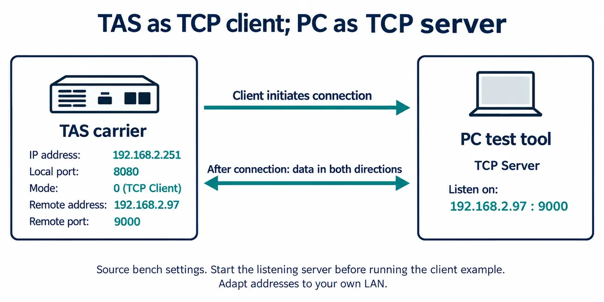
NetBurner's discussion of client and server roles in serial-to-Ethernet devices explains the same point, though its product features should not be assumed for this module. Our terminal capture recorded the configuration responses and the exchanged data together. Keep both when checking your own prototype: the settings tell you which path you exercised, and the received data tells you whether it carried anything useful.
We then reversed the roles: the module in TCP server mode listening at 192.168.2.251:8080, and the PC connecting to it as a client. Choose the arrangement that matches real use. A device that reports to a known computer may open the connection; a device that waits for a local test program may listen. Neither is better in general.
A successful exchange still needs a message format
It is tempting to stop when "Data received!" appears. In our examples, though, the code sends that acknowledgement before reading and decoding the pending data. It shows a round trip; it does not show that a complete command was understood or acted on.
TCP is a byte stream, so one receive need not match one send. Your program needs a way to recognize complete messages and keep partial data for later. A line ending works for simple text readings; a length field or structured frame may suit other protocols. Python's Socket Programming HOWTO explains this boundary problem. Choose framing that fits the existing serial device instead of inserting pauses and hoping they separate messages.
We also tested the module's UDP modes, which exchange datagrams without a TCP connection. Our configuration listed both endpoints, which is a good check against sending to the right address but the wrong port. The UDP exchange worked under our conditions; it says nothing about delivery under packet loss, retries or late responses. Those behaviors should follow from what the receiving application needs.
Use HTTP when the receiver expects a request
For the HTTP test we ran a small Python HTTP server on the PC at port 8080 and put the module in HTTP mode. With GET, the PC logged the request and the serial side received an HTTP/1.0 200 OK response with HTML. With POST, the server logged the posted test text and the response came back to the serial side. That is a local request and response demonstration, not an authenticated cloud integration or proof of compatibility with a production API.
For a dashboard or logging service, start from the receiver's contract: method, endpoint, payload format, authentication and expected response. Then check which parts the module and firmware can provide. An HTTP mode alone does not settle those questions; a local server is just a convenient way to watch the request first.
Make the next test resemble somebody else's working day
Once the basic exchange works, repeat it under ordinary disruptions. Restart the PC program. Unplug and reconnect the Ethernet cable. Power-cycle the module. Send two commands close together, and split one message across several writes. Record whether the application recovers, how it recognizes stale data and what the user sees while communication is down. We have not run these tests yet.
The physical arrangement needs the same attention. On the bench the board and cable are easy to reach. In an enclosure, leave room for the RJ45 plug and its latch, a sensible cable route, and access to configuration or recovery. Confirm those with the real connector and enclosure before a small run.
The result to aim for is an interface another person can reproduce: known wiring and serial settings, clear network roles, a documented message format and observed recovery behavior.