
You tilt a handheld controller and numbers move on a laptop. The sensing part of your idea is working. Now you add a button, a display or a sound response, and discover that everything depends on the next sensor reading arriving on time.
For a design team building a motion-controlled object, that is a useful point to pause. A sensor that calculates angles for you can simplify the first demonstration. Your software still needs to recognize complete messages, interpret them correctly and keep the rest of the interface running when an update is late.
On our bench we connected a GraftSense JY60 motion module to a GraftPort-RP2040 controller board, ran a MicroPython receiving program, and rotated the module by hand. This note follows that test and the gap between displaying angles and using them in an interactive prototype.
Start with the movement your product needs
A tilting exhibit control might only need to distinguish left, center and right. A handheld musical controller might map an angle to an effect while a button changes modes. Neither needs a promise of precise navigation to begin with.
Write down the response in those terms before choosing a headline accuracy number: which movement matters, what should change, and what should happen when the reading stops? A continuously updated terminal is useful evidence, but a person using the object needs the button and feedback to stay responsive too.
Serial framing is a recurring development problem. In a MicroPython community discussion opened in January 2024, a developer could receive bytes but sometimes read from the middle of one message into another. That concerns a different device; it illustrates the integration problem rather than anything specific to this sensor.
Follow the signals, not just the connector names
The test used UART1 at 115200 baud, with controller GP8 transmitting and GP9 receiving. On a UART link, one device's transmit signal goes to the other's receive input. The carrier labels need care: its MTX is the sensor's RX, and MRX is the sensor's TX. So the connection is GP8 to MTX and GP9 from MRX.
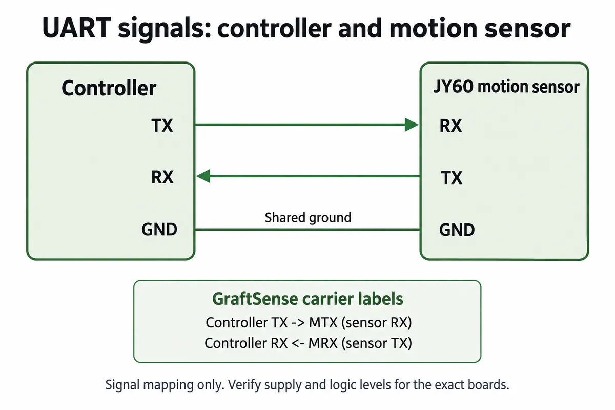
The diagram shows signal direction only. Use the board documentation to confirm supply and logic levels before connecting a different controller; a supply voltage label is not a specification for every signal pin.
A second UART, UART0 on GP0/GP1, was configured separately to send formatted angle text to a host computer. Those are two different links: the sensor's binary messages are not the comma-separated text sent onward.
Our receiving code used version 0.1.0 of our serial IMU driver. Constructing its IMU object also sends yaw-zero and accelerometer-calibration commands, with a delay after each. Startup therefore changes the sensor's reference; it is not a passive connection step. Keep the module still during power-up, and decide whether automatic recalibration suits the way users will switch on your object.
What the test program does
After a three-second delay, the program configures the two serial ports and an indicator LED. Each loop turns the LED on, calls the driver's receive function, turns the LED off, prints three angles and available memory, then sends the angles onward as text with two decimal places.
The terminal record showed changing X, Y and Z values and timings for the receive function while the module was rotated by hand. That shows a working assembly and reading workflow. It does not establish angular accuracy, a sustained update rate or behavior when the sensor cable is disconnected. The printed receive-function timing is also narrower than the delay from a person's movement to a display or sound response, which includes the rest of your application.
Turn a stream of bytes into a usable reading
The sensor protocol uses an 11-byte frame: 0x55, a type byte, eight data bytes and a checksum. Types 0x51, 0x52 and 0x53 identify acceleration, angular rate and angle data. The checksum is the low eight bits of the sum of the first ten bytes, an additive checksum.
"Bytes available" does not mean "one complete angle message available." MicroPython's UART documentation for v1.23.0 distinguishes buffered characters from a read, which can return fewer bytes than requested or None on timeout. The receiving code must keep partial messages and decide when it has enough valid data to use.
Inside an apparently reasonable number there is another detail. The protocol specifies signed 16-bit values, but our archived driver combined each byte pair as an unsigned number. The angle word 0xF000 means −22.5° when read as signed; the archived calculation gives 337.5°. Those can describe the same direction on a circle, but they behave very differently in a simple threshold or a linear effect mapping. Choose the intended range explicitly.
We replayed synthetic bytes through the archived driver offline, without the sensor attached. That reproduced the 337.5° result. It also exposed a receive-state problem: after the first complete set, the function returns before resetting its byte counter, and with one more synthetic set supplied it did not return a second result before our harness stopped polling. This was a software replay, and we cannot say which driver revision produced the earlier terminal record. The lesson is to check the exact driver you will build on; a successful screen of numbers does not qualify every code path for repeated use.
Keep the interaction alive when a reading is missing
In this driver, the receive function loops until it has all three data types. The configured five-millisecond UART timeout does not put a five-millisecond deadline on that outer loop. If a required message never arrives, the rest of a single-loop application can stay waiting.
For an interactive prototype, give reception a bounded amount of work per application cycle:
- accumulate incoming bytes and keep partial frames;
- validate the header, type and checksum of each complete frame;
- save the latest usable result with its reception time, then return control;
- mark a reading stale when its age exceeds a limit chosen for the interaction.
Do not silently present an old angle as a new movement. Also, separate acceleration, rate and angle messages should not automatically be treated as one simultaneous sample. If you only need a tilt control, establish reliable angle handling before making broader motion-tracking claims.
Test the behavior a person will notice
Once the parser is corrected and its version recorded, repeat the connected-module test. Move through both positive and negative angles while using the other controls on your prototype, and check the response across the angle range your application uses, including any wrap boundary.
Next, interrupt the incoming data and restore it. The useful result is more than "the sensor works again": the interface should stay responsive, handle missing data deliberately, and resume only from valid messages. We have not run these tests yet.
A short test record can capture the movement, the visible response, the age of the last valid reading and the recovery behavior. Set acceptable delays from the intended experience rather than treating the UART baud rate as a responsiveness claim. That gives a designer and a firmware developer something concrete to review together.