
Your prototype sends a command to a motor controller, then switches to listening for a reply. The command function returns without an error, but the reply never arrives. Before changing the cable or adding a longer delay, ask what that return actually means: did the software hand over the message, or has the last bit left the pin?
The distinction matters when integrating serial peripherals into a robot, an interactive exhibit or a test fixture. A plain UART link transmits and receives on separate wires; a half-duplex interface takes turns. Switching direction too early cuts off the command. Switching too late misses the start of the reply.
On our bench we sent the same short message through a PIO-based transmitter and through the RP2040's hardware UART, and timed how long each Python function took to return. Reading those numbers carefully leads to a better integration question than "which one is faster?"
Set up a message you can recognize
A USB-to-serial adapter and a PC terminal received UART TX DATA\r\n. The last two characters are carriage return and line feed, so the message is 14 bytes of ASCII.
Both transmitters ran at 115200 baud, and the receiver used eight data bits, no parity and one stop bit (8N1). Each byte therefore takes ten bits on the wire: start, eight data bits, stop. At the nominal rate, fourteen back-to-back bytes take about 1.215 milliseconds, before any gaps between characters. That is a calculation, not a waveform we measured.
One setup detail needs resolving before you reproduce this. Our preparation notes listed GP8 for PIO transmission, but the program sets PIN_BASE = 4, which puts the PIO transmitter on GP4. The hardware UART used GP0 for TX and GP1 for RX. Check the actual program and board pinout, connect the selected TX to the adapter's RX with a common ground and compatible logic levels, and test one output at a time. Never join two TX outputs.
Follow the character from the queue to the pin
PIO is the RP2040's programmable input/output hardware. Here a short PIO program drives the TX pin while Python feeds it characters. The helper follows the Raspberry Pi PIO UART example (BSD-3-Clause):
def pio_uart_print(sm, text):
    for character in text:
        sm.put(ord(character))
Each call puts a character value into the state machine's transmit FIFO, a small first-in, first-out queue. If the queue is full, put() waits for space. Once the last character is in the queue, the helper returns, even though the state machine still has work to do. The StateMachine documentation describes that queue behavior. An empty FIFO also does not prove that the character already loaded into the output register has left the pin.
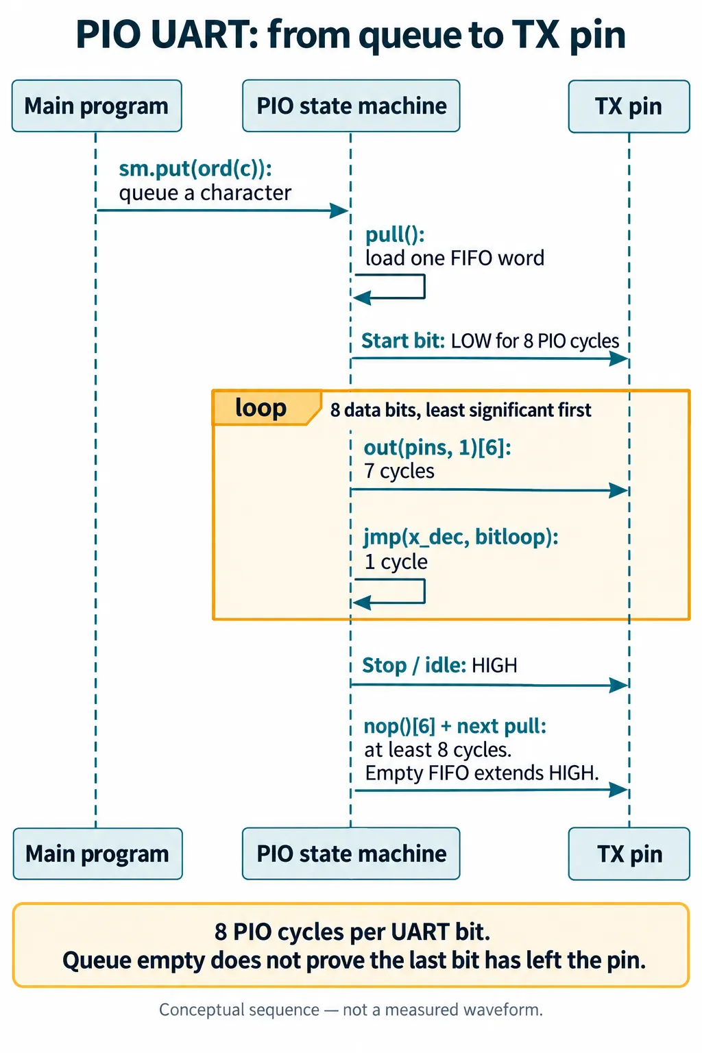
The state machine runs at eight times the bit rate. It pulls one word, drives a low start bit, shifts out the low eight bits least significant first, then drives the stop bit high. Each data bit is seven cycles for the delayed out instruction plus one for the loop jump. The stop interval includes the next pull, and an empty queue simply extends the idle-high period. The Raspberry Pi example uses the same sequence, but its pins and number of transmitters differ, so check your own assignments.
Read the two timing results as different measurements
Before any changes, one PIO call took 0.924 ms and one hardware-UART call took 0.127 ms, with small variation on other lines. Both are shorter than the nominal wire time for the full message. The 0.127 ms figure does not show fourteen bytes crossing a 115200-baud link; it shows how long the function held up the caller.
We then added a wait after the hardware UART write, a loop that keeps checking txdone(). The two console captures come from different revisions of the program, not from identical code.
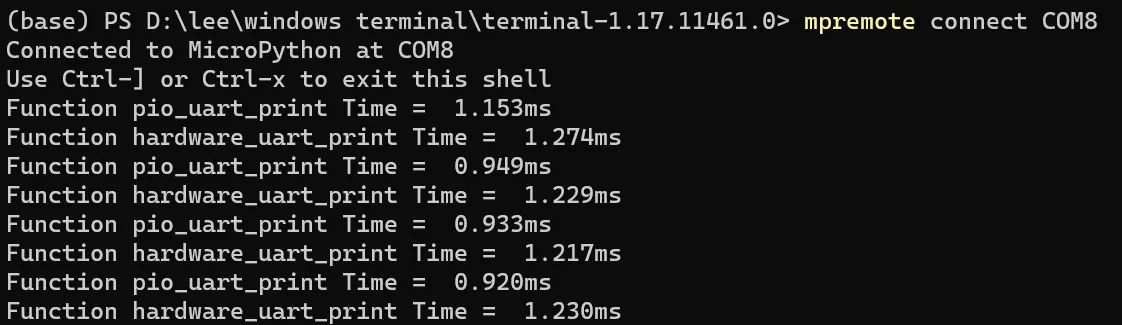
With the wait in place, the hardware-UART calls took 1.274, 1.229, 1.217 and 1.230 ms. The PIO helper still returned earlier on most lines. That is consistent with moving the point at which the hardware helper returns. It is not evidence that the PIO pin sends the same framed message faster.
There is a version detail too. The program targeted MicroPython 1.23.0, whose UART documentation warns that the RP2 port can report txdone() while the final byte is still being sent. A later upstream correction checks that the hardware is no longer busy, and the 1.24.0 documentation no longer lists RP2 under that caveat. Timing close to the calculated value is useful context, but these console numbers cannot show exactly when the last stop bit ended.
Confirm reception, then test the handover
The PC terminal received the repeated UART TX DATA messages with the expected settings. That confirms visible reception. It does not measure last-bit timing, and it is not a test of a peripheral that replies immediately after a command.
What to test next depends on what your prototype does after sending. If it only prints occasional diagnostics, carrying on while the UART finishes may be fine. If it disables the interface, cuts power or switches a shared line from transmit to receive, the completion point is part of the design. Check the exact firmware's completion API and verify the transition with the real peripheral. Do not assume a fixed delay copied from another board still fits after a firmware update.
That last point has a concrete example. In a December 2025 Pimoroni support discussion, a Yukon user lost serial-servo responses after a firmware update. The maintainer traced one cause to an old compensating delay that now made the transmit-to-receive switch too late. Removing it helped but did not end intermittent failures, and interrupt-based changes followed. The user later reported improved operation with an occasional remaining error, not complete reliability.
Give the engineer a clear acceptance test
For a device that must send and then listen, record the exact command, baud rate, frame format, firmware build and expected reply. Capture three moments on a logic analyzer: the final transmitted bit, the direction-control change where there is one, and the first received bit. Repeat with the shortest and longest expected messages and under normal application load. We have not yet run that capture; it is the next step after this timing test.
A completed send also does not prove that a motor moved or a setting changed. If the product needs confirmation, define the acknowledgment or readback that proves it, and keep that separate from the lower-level question of whether transmission has finished.