
A sensor sends a temperature, distance or particle reading that looks reasonable, but the driver reports a checksum error. It is tempting to switch the check off and keep building the display. The risk is that the prototype then treats a record it cannot validate as an ordinary measurement.
Start by finding out why the check fails. The wiring may be involved, but so may the software's interpretation of the message. In an April 2016 SDS011 discussion, every packet failed the author's checksum test. The author later confirmed that reducing the sum to eight bits fixed the comparison. That was a software mistake, not a sign that every checksum error calls for new hardware.
This note separates three common checks on serial links (parity, CRC and XOR) and distinguishes a single transmitted character from a complete sensor message. The examples are arithmetic, not results from an error-injection test; they show what to verify in your own protocol.
Parity does not validate the whole measurement
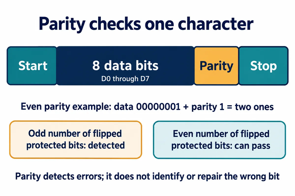
A UART parity bit checks the data bits in one character. With even parity, the data and parity bit together contain an even number of ones. An odd number of flipped bits within that group changes the parity; an even number does not. Microchip's explanation makes that limitation explicit. Parity alone also cannot tell you which bit to repair.
So the receiver can accept several individually valid characters that do not form the intended message. A record could be incomplete, duplicated or read with the wrong field layout. The application still needs message boundaries, the expected length and the module's documented validation rule.
If you are integrating an existing sensor, use the rule it actually specifies. A byte sum, an XOR checksum and a CRC are different calculations. Picking whichever method happens to make a few captured messages pass is not a substitute for the protocol definition.
"CRC-16" is not enough information to implement a check
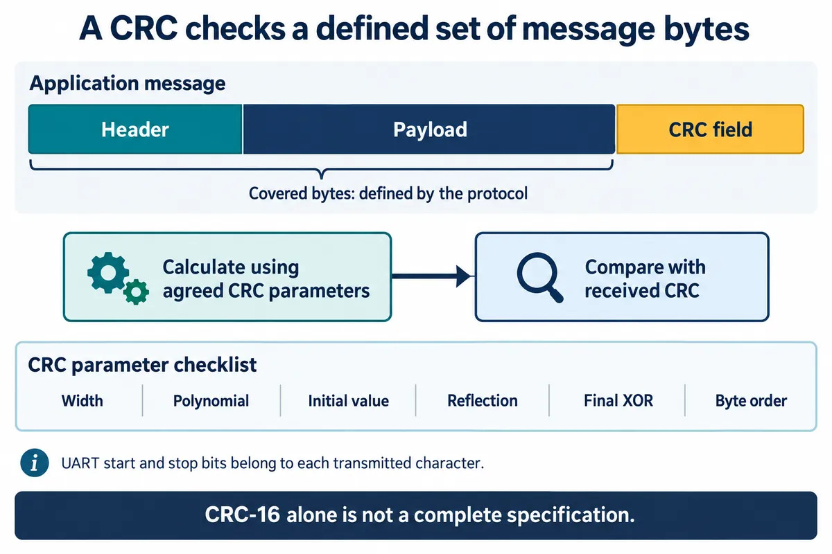
A CRC is a compact check value calculated over a defined sequence of bytes. To reproduce it, both ends must agree on more than its width: the polynomial, initial value, input and output reflection, final XOR, the fields covered and the order in which the result bytes are sent. Infineon's CRC documentation lists the parameters and byte-order handling that change the result.
The practical request to a module supplier is simple: the exact algorithm, plus at least one complete example message with its expected check value. Test that known message on its own, away from live hardware. If your calculation disagrees with the documented example, fix the implementation or clarify the specification first; moving wires will not resolve that.
A passing CRC does not prove every error was absent. Detection depends on the algorithm, message length and error pattern. It also says nothing about whether the sensor is calibrated, the value is fresh or the sender is authorized. Do not describe a CRC as encryption, authentication or a measurement-quality guarantee.
Keep the raw bytes when a record is rejected
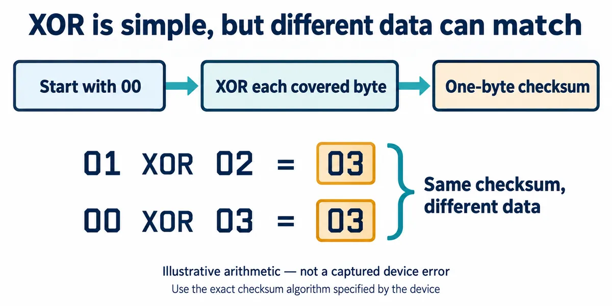
The bytes 01 02 XOR to 03, and so do 00 03. Two bit changes can cancel in this check, and swapping the order of the same bytes leaves the XOR unchanged. These are arithmetic examples, not captured faults, but they show why a simple checksum has to be understood rather than merely enabled. A name such as "LRC" in a module manual is also not enough to pick the algorithm; follow the definition the manual gives.
When the real device fails validation, save the complete received bytes, their length, the received check value and the value your program calculated. Note the serial settings and which fields the calculation covered. Work on the bytes themselves: converting them to printable hexadecimal text before calculating gives a different input unless the protocol requires that representation.
Then look at the failure pattern. Does every packet fail with the same implementation? Did it start after a firmware change? Does it appear only when the cable moves or the sender runs faster? These observations guide the investigation; none of them alone proves a cause. Count rejected records so that retries do not hide a deteriorating link.
Define what happens to the rejected reading
An invalid record should not silently replace the last valid one. A logger should keep the gap and the reason. A display should show that the last valid reading is old or unavailable. For an actuator, choose the failure behavior during system design rather than letting a corrupted value become a command by accident.
Before the next user trial, build a small validation set: one documented valid message, a copy with a changed data byte, one with a changed check byte, a truncated message and two messages arriving together. Write down the expected result for each. If retries are supported, test the retry limit as well. These are proposed software tests; a forum fix does not show that your prototype passes them.
The goal is a clear rule for accepting data, and a visible outcome when data cannot be accepted.