
Your first gas-sensor module is connected and sending numbers. The next prototype needs several sensing channels, perhaps for an environmental monitor that compares different responses. Adding more labels to the screen is easy. Making each label reliably describe the physical sensor behind it takes more work.
On our bench we went from a single digital GraftSense gas module to a four-sensor carrier on a GraftPort-RP2040 controller board running MicroPython. Both setups produced real console output. Together they answer three practical questions: which sensor is connected, how the controller reaches it, and whether the displayed value came from a successful measurement.
Establish what one module actually returns
The single module connected SDA to GP4 and SCL to GP5, using MicroPython's SoftI2C at 100 kHz. SDA carries data; SCL carries the clock. These are GPIO numbers, not header-pin numbers. The sensor's logic and heater supplies are separate inside the carrier, so use the board's documented connector supply rather than applying its input voltage directly to a bare sensor.
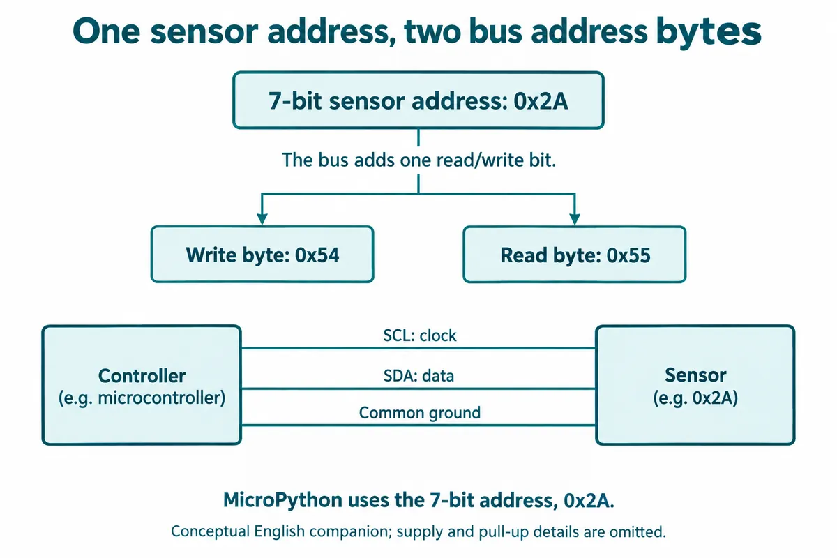
The module documentation lists an address of 0x54, while our program and scan used 0x2A. That is a notation difference, not a conflict. The seven-bit sensor address is 0x2A; the bus adds a read/write bit to make 0x54 for a write and 0x55 for a read. MicroPython's address arguments use the seven-bit value, as its I2C documentation explains.
A read sends command 0xA1, then receives two bytes, which the driver combines as high byte × 256 + low byte. That tells you how the number is assembled. Its meaning still depends on the fitted probe, its documented output and its operating conditions.
Our single-module run found 0x2A, waited 30 seconds and attempted zero calibration. The console then reported that calibration confirmation failed, with a returned value of 4018. The next message said the program would exit, but readings continued: the code printed the message without stopping the loop.
That is a useful distinction for your prototype: "the sensor answered" and "the calibration succeeded" need separate states. A user looking only at the final number would miss what happened during startup. Keep the failure visible in the interface or log, and decide whether later readings should be shown as provisional or withheld until the problem is resolved.
Add a route to each sensor
The four-sensor carrier adds a PCA9546A-family I2C switch. It connects the controller to one selected downstream branch, so sensors that share an address can be reached separately.
This is a familiar expansion problem. In a June 2019 Arduino Forum discussion, a builder wanted to connect two identical sensors and needed to distinguish another connector from another bus. A switch gives one upstream SDA/SCL pair and four downstream pairs. A branch is a selectable path; it does not give a sensor a new identity or make all channels measure at the same moment.
In our multi-sensor driver, the switch defaults to seven-bit address 0x70. Before reading a sensor, the program disables all branches, selects that sensor's branch and sends the read command. The single-channel control values are 0x01, 0x02, 0x04 and 0x08 for channels 0–3.
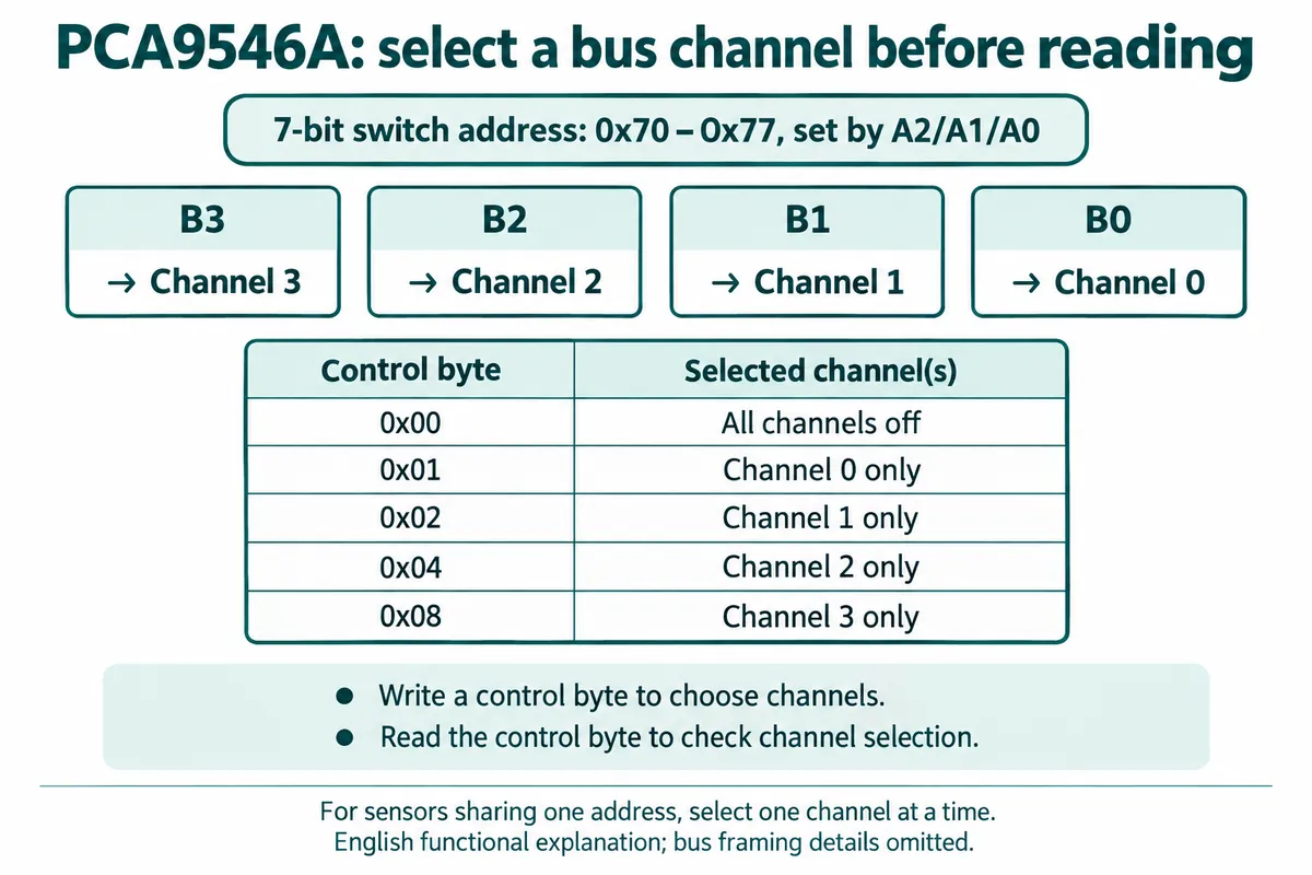
TI's PCA9546A datasheet, section 9.1, describes reading same-address devices by enabling the wanted channel and switching the others off. Check the actual fitted switch and its own specifications when building a board; a shared part-family name is not a full electrical compatibility check.
Match the screen labels to the fitted probes
The carrier artwork labels its four positions VOC, HCHO, CO and SMOK (HCHO is formaldehyde; SMOK is the board's smoke label). Our test program registered VOC, CO, H2S and NO2 on channels 0–3. Those lists do not describe the same sensing functions.
Changing a software name does not change what a probe senses. In this driver, the gas-type setting is a label used to organize objects and results; every read sends the same command and combines the same two reply bytes. Before handing the prototype to someone else, match each probe's part marking to its board position, switch channel, output unit and displayed name, and keep that mapping with the wiring photo and firmware version.
If the design later uses two probes of the same type, review how the software identifies them. This driver's lookup is keyed by gas type, so registering a second sensor of the same type replaces the first one's channel entry. Use a location or channel identifier when two physically different readings must stay separate.
Make an unavailable reading look different from zero
The multi-sensor console printed four names, but its startup record included another failed zero-calibration confirmation, for the VOC-labeled channel, with a value of 610. Later it displayed VOC as 589 and the other three entries as zero. That is what the program printed; it is not four validated gas concentrations.
There is a software reason to keep status visible. The driver's read method catches an I2C error, prints a message and returns 0. A display that keeps only the returned number can make a failed transfer look like a legitimate zero. We cannot tell from the log whether that caused the three zeros, but the code path has to be fixed before relying on them.
Treat each displayed result as a small record: sensor or channel identity, value, unit, time and status. After a transfer failure, the interface might show "Channel 2: unavailable" while keeping the last successful value with its time if that helps the user.
Calibration needs the same treatment. Our test called the calibration methods without acting on their success or failure. Check those return values and the underlying transaction handling before the interface reports a ready state. The driver is a development tool, not a finished measurement subsystem to adopt unchanged.
Test the whole path before adding the enclosure
Begin with one identified probe on one known channel. Record the selected channel, detected address, raw reply and displayed result together. Then repeat for each fitted probe, checking that every software label follows the intended physical position. At this stage you are verifying routing and interpretation, not gas accuracy.
Next, run a controlled fault check: power down, disconnect one module, restart, and confirm that the missing channel shows as unavailable instead of a reassuring zero. Test startup, unsuccessful calibration and recovery as separate cases. We have not run these checks yet.
Once that path is dependable, enclosure, airflow, operating conditions and application-specific measurement validation can build on a clear record. A multi-channel communication demo is real progress, but it is not a qualified gas alarm or a finished environmental instrument.