
Your prototype's display works on its own. So does the extra serial interface. Put their software together, though, and one signal stops changing, or changes when the other module starts. Before replacing the board, check whether the two pieces of code agree about who controls each pin.
On an RP2040, programmable I/O (PIO) lets small hardware programs run interfaces independently of the main application. That flexibility helps during integration, but a PIO program's instructions do not all share one pin setting. Switching from one output instruction to another can need a matching configuration change, even when the physical wire stays where it is.
This note explains that relationship and turns a set of working demos into a pin assignment that hardware and firmware can both follow. It is based on the RP2040 and MicroPython references, not on a completed integrated product.
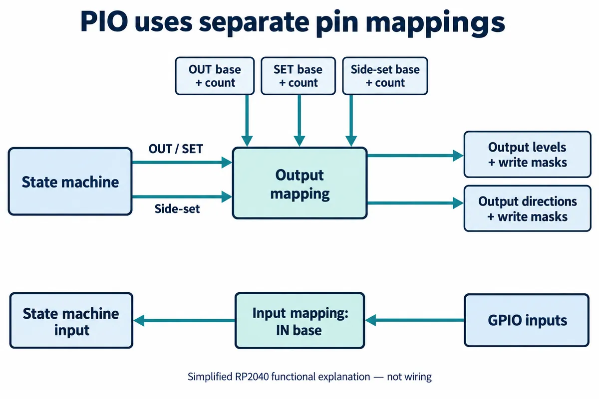
Match the configuration to the instruction
In MicroPython, set_base gives the starting pin for set() operations, while out_base serves out(). Side-set, the extra pin operation attached to an instruction, has its own sideset_base. The program decorator also configures the corresponding pins through set_init, out_init or sideset_init. Change the instruction but leave the old configuration, and you can end up watching the wrong output path. MicroPython's PIO reference documents these parameters.
A Raspberry Pi forum thread from April 2023 is a concrete example. A developer could switch a pin with set() but got stuck after sending values through out(). The discussion pointed to the missing OUT initialization and mapping, and the developer later reported it working. That is a useful clue, not a guarantee that every silent pin has the same cause.
Make the mapping visible in the project notes. For each signal, record the board connector, GPIO number, software owner and instruction path. "Display data" is a useful signal name; "pin 4" is ambiguous unless everyone knows whether it means a header position or a GPIO number. Also record how many adjacent pins the operation uses: PIO's configurable ranges do not let every instruction control an arbitrary scattered group. For each signal, the record should say:
- Data output: GPIO range, owning state machine, OUT or SET mapping and direction.
- Clock or extra control output: its separate mapping, including side-set if used.
- Data input: GPIO range and IN mapping.
- Conditional input: the pin used by the particular wait or jump instruction.
Inputs need the same care. in_base sets the input mapping, while jmp_pin names the pin tested by a conditional jump. On the RP2040, WAIT GPIO uses an absolute GPIO number, so moving a signal's IN base does not relocate every reference to that signal in the program. The StateMachine documentation lists the configuration parameters; use the version that matches the installed firmware when reproducing an example.
A second state machine can change the result
Now put two state machines in the same PIO block. Each can write pin levels and directions. If their assignments overlap, the hardware applies defined priority rules; it does not ask which peripheral you meant to control. Within a state machine, side-set wins over an overlapping OUT or SET in the same cycle. Between state machines in one block, the highest-numbered one writing that GPIO in that cycle takes priority, with level and direction resolved separately. RP2040 datasheet section 3.5.6 describes these rules.
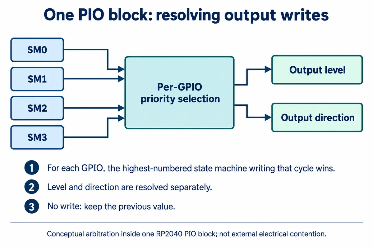
That explains why a demo can work alone and fail once another program starts. It also shows why moving one program to a higher-numbered state machine is a poor repair: the overlap is still there, and the result still depends on which code writes when. For independent interfaces, give each output one clear owner. Deliberate sharing needs an explicit hand-over design, including pin direction and idle state.
The internal priority logic does not make it safe for two external devices to drive the same wire against each other; check the electrical connection separately. A pin map also does not prove that a GPIO is free on the development board, because onboard peripherals and connector wiring still matter. Use the board's schematic or pinout alongside the program configuration.
Isolate the change before redesigning the hardware
Start from the last working single-interface setup and its exact initialization. With the intended connections checked, watch the signal at the GPIO or an accessible test point. Then enable the second interface without changing the wiring. If the first signal changes at that moment, compare the two initialization paths and their complete pin ranges, including directions and side-set assignments.
If the problem began when set() was replaced by out(), review the program and its configuration together. If it began after a wire was moved, check every instruction that reads or tests the old pin. A logic trace then tells you whether a waveform is absent, on a different pin or simply wrong. Each observation narrows the next change; adjusting the whole program at once throws that information away.
Keep the final pin assignment with the firmware revision and the wiring drawing, and recheck it when adding a module or changing boards. The goal is not just that both demos run once. Another person should be able to identify each signal's owner and reproduce the combined setup without guessing.