
Your environmental monitor has several sensor modules sharing the same two communication wires. Each module works on its own. After combining their drivers, a restart of one sensor appears to disturb another. Before replacing a module, inspect the command used by the reset routine: does it name one device, or address the bus more broadly?
This matters for teams turning a collection of working demonstrations into one product prototype. In a public embedded-development discussion, accessed October 10, 2026, a developer questioned writes to reserved I2C addresses after finding a CO2 sensor that responded to a general-call reset. The discussion exposes a real integration assumption: an address that looks unused may have a defined purpose.
This note is a protocol review, not a recording of several sensors being reset together. It gives you a way to inspect the commands in a combined prototype without assuming every device behaves alike.
Find out how wide the reset reaches
A normal addressed command selects a particular I2C target. A general call uses the reserved address 0x00 with a write operation. The second byte defines the action; 0x06 requests software reset on devices that support it. The feature is optional. A device can ignore the call, so it is not a universal reset button for everything connected. These rules are described in NXP UM10204, sections 3.1.13 and 3.1.14.
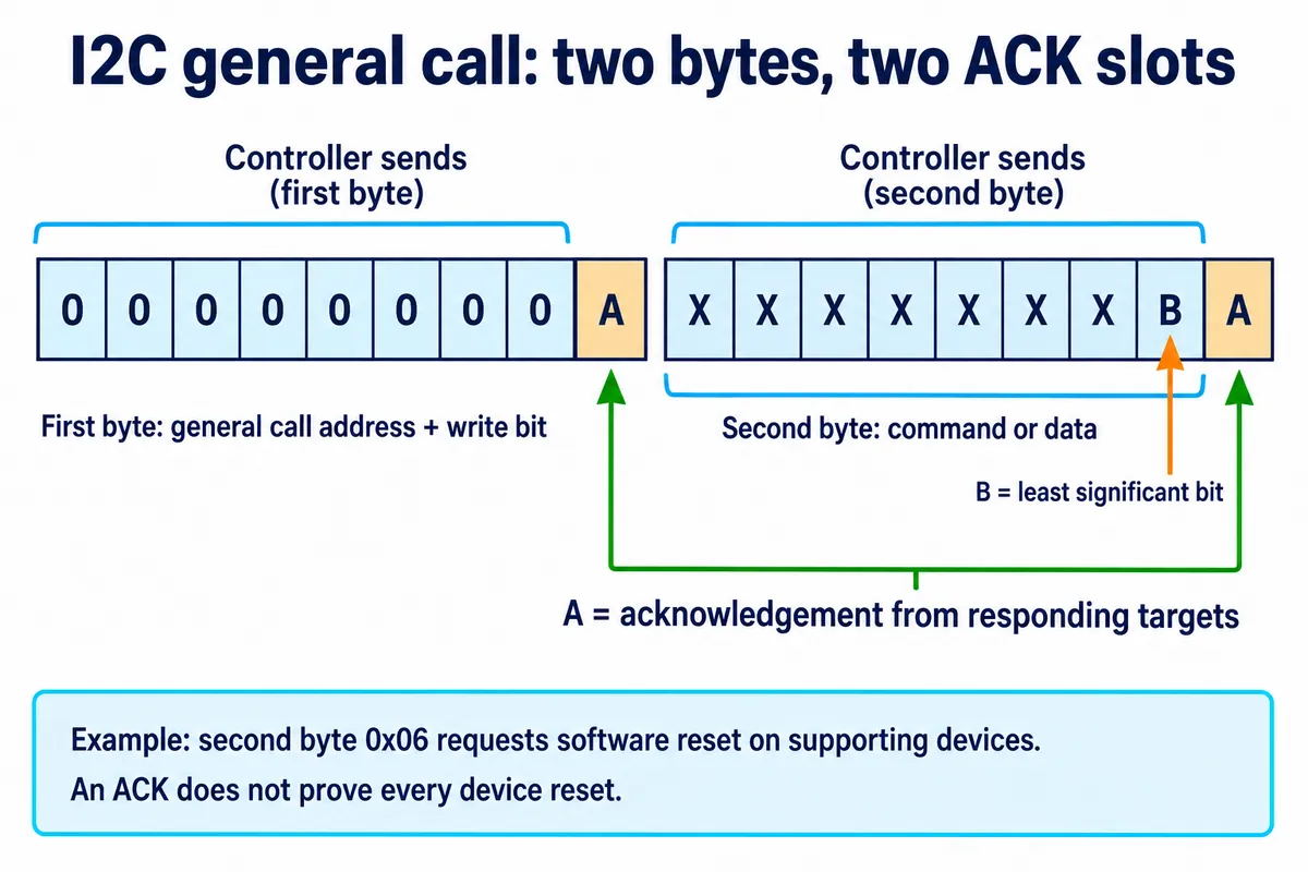
Nor does an acknowledgement count the responders. Several devices share the acknowledgement line, so one responding device is enough for the controller to see ACK. That response cannot establish that every intended device received the command or returned to the required state.
For the integration review, list the devices on each bus and the reset operation their drivers actually send. Include startup routines as well as error-recovery code. A function called reset_sensor() may still contain a general call; its name does not tell you the scope of the underlying transaction.
A device may offer a more targeted option
The Sensirion SHT4x datasheet, version 7.3, lists both a device soft-reset command, 0x94, and general-call reset using 0x06 at address 0x00. These are different ways to reach a reset. For a reset intended only for that sensor, the addressed option is worth evaluating against the driver's behavior and the complete device documentation.
That example is not a command recipe for an unrelated module. Other parts can provide different commands, a reset pin, or different limits on which operating states accept a command. Check the exact part and its required sequence. The engineering choice is to reset the intended device while understanding any effects on the rest of the assembly.
The same review should identify what the reset changes:
- Does the device lose its configuration?
- Must measurement be started again?
- Does it need time before a usable reading exists?
The answers belong in the initialization sequence, rather than being guessed from the next successful bus transaction.
Successful communication is only the first checkpoint
In a TI support exchange about TMP100-Q1, the customer asked how long to wait before reading temperature after a general-call reset. TI's answer distinguishes reset from measurement: wait at least one conversion period; the temperature register reads 0 °C before the first conversion completes. That is device-specific guidance, not a universal delay for every sensor.
For a prototype user, the consequence is simple. A number that can be read successfully may still be a startup value. During recovery, show that the reading is unavailable or initializing until the relevant checks pass. Do not present the first returned number as a fresh measurement merely because the bus has started responding again.
This is also why a broad reset should not be silently added as a retry for every error. If other devices respond, they may need their settings and measurement state restored too. Decide which recovery behavior the application owns, then verify it with the complete set of modules connected.
Test the combined sequence before the next user trial
Start with a written expectation: which device should reset, which neighboring functions should continue, and what the user should see during the interruption. Save the relevant settings and status observations before the test. Exercise the actual startup or recovery path, then check each potentially affected device individually.
Record the command address and data, any required waits, the restored configuration and the first valid result. If the observed scope is wider than intended, investigate a documented device-specific reset or a change to the integration design. If the whole bus is stuck, that is a separate recovery problem: sending a valid reset transaction presumes communication is still possible.
The useful outcome is a repeatable recovery sequence for the assembled prototype, with no unexplained change in neighboring functions. Those are proposed checks; we have not run them on a specific multi-sensor build for this note.