
Your prototype already works when someone turns a knob. Now you want a phone app, a stored preset or an automatic adjustment to do the same job. A digital potentiometer such as the DS3502 looks like a straightforward replacement. First you need to know what the existing knob actually controls: a resistance, a voltage, or something inside a larger circuit.
That distinction decides whether a module will work at all. On our bench we drove a GraftSense DS3502 module from a MicroPython controller and watched the result on a plotted waveform. It shows how software changes a digital potentiometer, and why a waveform on the bench is only the first step toward replacing a control in a product.
Start with the job the knob is doing
An Arduino user described this problem clearly in November 2023: a software engineer on a first project wanted to replace an LED dimmer's variable resistor. The DS3502 could change the light level, but its 10 kΩ range was too small for the adjustment they needed, and the discussion moved to other control methods. It was a question about matching the light's control input, not about making an I2C command work. Read the discussion.
The reason for the change matters too. In a 2026 SparkFun thread, a maker considered digital potentiometers because people kept pulling knobs off an RGB light panel. Better mounting or tougher controls were also possible answers; adding a microcontroller does not stop a knob from being pulled off. Read the light-panel discussion.
Before choosing a part, identify the existing control's connections, resistance range and terminal voltages, plus what should happen at switch-on and if the controller stops responding. That turns "make this knob digital" into a testable integration task.
What changes when the control becomes digital
A mechanical potentiometer moves a contact along a resistive track. The DS3502 selects one of 128 positions electronically, codes 0 to 127, set by a microcontroller over I2C. That makes repeatable commands and stored startup settings possible, within the chip's electrical limits.
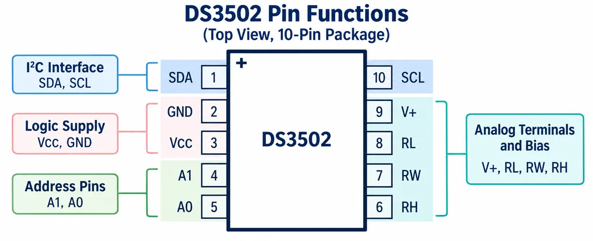
The chip needs power for its logic and a separate analog bias supply. A terminal that survives a voltage under its absolute-maximum rating is not automatically fine at that voltage in normal operation. Use the recommended operating conditions and current limits in the DS3502 datasheet.
This particular module adds a twist. Its schematic routes the chip's wiper through an LM358 amplifier configured as a buffer before the terminal labeled RW. A buffer gives a voltage output; it does not expose the passive resistance of the bare wiper. So this board should not be assumed to replace a two-wire variable resistor just because both are called potentiometers.
That makes our test a programmable-voltage demonstration. For a resistance-controlled input, you would need a circuit that exposes the required resistance terminals. For a voltage-controlled input, check the buffer's actual output range, loading and supply. Neither decision can be made from the module's name.
The bench run
The setup was the DS3502 module, a MicroPython controller with an expansion board, an ADC input and a USB-to-serial link. The program repeatedly changed the wiper setting, read a voltage and sent text values at 115200 baud to SerialPlot on a computer. Sine, square and triangle patterns made it easy to see whether the output followed a changing command.
For the analog side we used a separate supply: ground at RL, +5 V at V+, and the module's switches set to connect RL to ground and V+ to RH. A multimeter read about 5.02 V at the supply. That reading does not establish the full range of the buffered output.
Treat this run as a record, not a verified wiring recipe. Our wiring notes, code and ADC-channel descriptions did not fully agree; the software's voltage conversion assumed 3.3 V while the supply was 5 V; and the module's schematic notes an earlier amplifier-related output problem. Before reproducing it, reconcile the board revision, measure the output range and confirm the ADC input's protection and limits. Do not connect a possible 5 V signal straight to a 3.3 V ADC input.
Make the first software check small
The A1 and A0 pins select one of four 7-bit addresses, 0x28 to 0x2B. On this module they are set by solder links; inspect them with power off, then scan the bus. Finding the address confirms communication, not correct analog wiring.
The DS3502 keeps the current wiper setting separate from the nonvolatile value it restores at power-up. During repeated adjustments, select the mode that writes only the current setting; otherwise every write also updates EEPROM, which brings timing and endurance into play. With i2c already configured for verified wiring:
address = 0x28                                   # A1 = A0 = 0
i2c.writeto_mem(address, 0x02, bytes([0x80]))    # write current setting only
i2c.writeto_mem(address, 0x00, bytes([64]))      # near midscale
print(i2c.readfrom_mem(address, 0x00, 1)[0] & 0x7f)
Reading back 64 shows the register holds the requested code. It does not prove a voltage, resistance or brightness; measure the physical output separately. We checked this sequence against the register description but did not run it on our hardware.
Once single settings behave, a slow sweep tells you more than attaching the final load straight away. Check both ends and several points in between. Then switch the module off and on: a product that remembers a setting needs a deliberate startup policy, not whatever value was last saved during development.
What the waveforms show, and what they do not
The program stepped through a 50-point waveform table, and the plotted traces changed shape between sine, square and triangle as requested. That is useful evidence that the control path works. It is not a measurement of how a lamp, motor controller or instrument would respond, because no such load was attached.
Two timing details limit the plots. The code requested 5 Hz while its printed message said 10 Hz, and the ADC timer used a 10 ms period although a comment said 1 ms. Those describe the program; the plots alone do not establish output frequency or timing accuracy.
The traces also showed visible steps. The chip's finite positions, the finite waveform table and separate ADC samples can all contribute; the plot cannot separate them. A smooth-looking line in a plotting tool is not continuous adjustment or a precision waveform source.
During one recording the console reported RuntimeError: schedule queue full: the acquisition callback was scheduling work faster than the program could consume it. So a visible waveform does not prove uninterrupted sampling. For a product test, reduce or restructure the acquisition workload and count missed samples before judging timing from a plot.
For a dimmer, the practical question is whether people notice jumps or flicker in the useful brightness range. For a calibration control, it is whether the available steps and repeatability meet the requirement. The same part can suit one job and not another, and a 400 kHz I2C clock rating does not mean it can generate a 400 kHz waveform.
Decide whether the module belongs in your prototype
If the circuit needs a variable resistance, check resistance range, wiper resistance, terminal voltages and current against the chip and the actual board connections. If it takes a control voltage, check the complete output circuit, including any buffer. The original knob may also have a response curve that a linear sequence of codes will not reproduce.
If the goal is remote presets, list the few operating points that matter and test them on the real interface. If the goal is surviving public use, test the mechanical control and mounting too. And if the receiving device already has a documented digital or PWM input, compare that route before redesigning its analog control.