
A prototype can run smoothly at two different settings and still stumble when you move between them. A brief twitch, click or unexpected output during adjustment is easy to miss if you check the waveform only after it settles. For a team preparing a responsive device for user testing, the transition deserves its own test.
Pulse-width modulation, or PWM, controls an output through repeated high and low intervals. The frequency describes how often the pattern repeats; the duty cycle describes how much of each period stays high. Changing either while the timer is running raises a practical question: when does the new value become active?
A Raspberry Pi forum report from August 2023 describes an RP2040 ultrasonic-driver project that produced a brief disturbance when the frequency changed. The author later reported improvement using a different update method. It is an older, specific report, not a diagnosis of your board. It does illustrate why a good steady output is only part of the check.
This note uses the RP2040 as the example. We did not capture output waveforms or load behavior for it; it explains what to test and why.
Let the current pulse finish its job
A PWM timer can be pictured as a counter that repeatedly climbs to a top value and returns to zero. A comparison level determines when the output falls low. If the next comparison level takes effect at the start of the next cycle, the current pulse finishes according to its old setting and the next pulse uses the new one.
One detail matters if you work at the register level: on the RP2040, a continuously high output uses a compare value of TOP + 1 where that value can be represented. Setting the compare value equal to TOP is not the same calculation.
Now imagine changing the active comparison level halfway through a cycle. The output may already have fallen low under the old threshold. Raising the threshold above the current count can make it go high again, creating a pulse fragment before the cycle ends. That is the failure buffering is designed to prevent. Seeing a glitch in a product therefore does not automatically mean its PWM peripheral lacks buffering; the cause may be elsewhere in the update path.
A write can be accepted before it affects the output
The RP2040 keeps a software-facing value and an active value for its period and comparison settings. In the RP2040 datasheet's description of double buffering, new values become active at a defined counter boundary. Software can prepare the next setting without cutting into the current pulse.
The consequence is a delay. If an interrupt handler writes a new compare value after one wrap, the output uses it from the following wrap. That explains a one-cycle lag in the hardware sequence. It says nothing about how quickly a MicroPython callback will run.
The Pico SDK 2.2.0 PWM API distinguishes the operating cases: a running PWM slice loads buffered period and compare settings at wrap, or at the zero boundary in phase-correct mode; a stopped slice takes the write immediately. A test made with the timer stopped therefore does not exercise the same transition as a live update.
Two buffered values are still two updates
Suppose you change both the period and the high time. Each value can be buffered correctly, yet software can write one just before the load boundary and the other just after it. For one cycle, the active combination may contain the new period and the old comparison level.
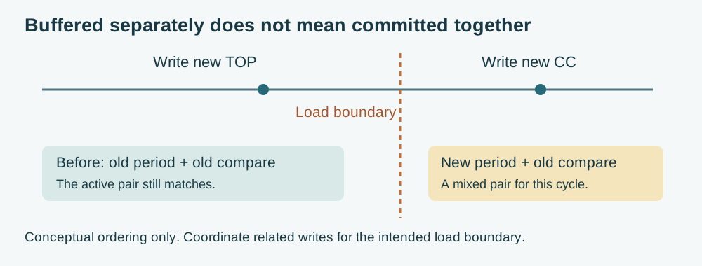
That is a coordination problem, not the mid-cycle comparison change described earlier. Establish how the API you use commits a related set of parameters, including whether it reinitializes the timer. Do not assume that two nearby function calls form one indivisible update because the underlying registers are buffered.
The software path has mattered before. An Arduino-Pico issue opened in October 2022 discusses unnecessary PWM reinitialization and a more targeted update. It should not be read as an unfixed defect in current releases. Use it as a reason to record the actual library version and inspect what its update function does.
Keep the first comparison small
Start by changing only the duty cycle while leaving frequency, pin assignment and operating mode fixed. Capture the signal around the requested change. Next, test the actual frequency change or combined update the product needs. Comparing the two cases separates a basic level update from a more extensive reconfiguration.
If you use a wrap interrupt or DMA to prepare values for a later cycle, the update still has a deadline. Test under the application's normal workload, not only in an otherwise empty loop. The hardware sequence explains the order of events; it does not prove that every handler finishes before the next boundary at every operating frequency.
Avoid changing several layers at once. Replacing the output driver, rewriting the control loop and switching PWM libraries in one revision can hide the cause. Keep a reproducible before-and-after capture and the exact parameter sequence, so the change is backed by evidence rather than another demonstration that happened to look fine.
Define what counts as a clean transition
For the intended device, identify the output that matters and the disturbance that is unacceptable. The acceptance test might look for an extra edge, an unexpectedly short pulse, an excessive gap or a downstream movement. A frequency counter or an average duty reading can miss a single malformed cycle, so put the transition inside the capture window.
Check both increasing and decreasing adjustments, the limits of the allowed range, and repeated changes while other features are active. Also separate the controller's pin from the driven load: a clean logic waveform does not rule out a supply, driver or mechanical problem further along. The result should tell you which part needs attention before the next prototype revision.
When you report the problem, include the board and firmware version, the old and new settings, and a capture around the change. Those details turn "it occasionally twitches" into a focused integration task.