
You want to take a small sensor or interactive device to a workshop and read its messages on a nearby laptop. There may be no router you can use. The device creates its own Wi-Fi network, the laptop joins it, and Windows says there is no Internet connection. Has something failed?
For a local connection, that can be exactly the expected result. A Wi-Fi network can connect two nearby devices without giving either a route to the Internet. In a September 2026 r/embedded thread, a student planning a connected robot mixed up a device's own Wi-Fi with Internet access. It is an easy distinction to miss when everyday Wi-Fi provides both.
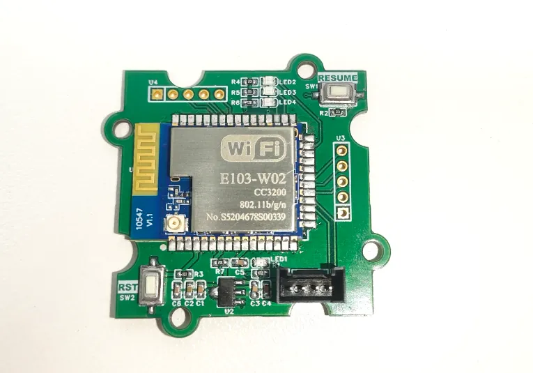
On our bench we connected a GraftSense board carrying an EBYTE E103-W02 Wi-Fi module to a GraftPort-RP2040. The RP2040 sent serial messages through the module to a laptop, and the laptop sent a message back. No cloud account was involved, and no cloud connection was established.
Decide which device creates the network
The E103-W02 can act as an access point (AP), creating the network the laptop joins, or as a station (STA), joining a network made by a router or hotspot. Those roles answer "who joins whose network?" They do not decide where your application data goes. Write down the role you intend and compare it with the role the device reports; a device that quietly starts its own AP when you expected it to join a hotspot is a common setup surprise.
We used AP plus NORMAL mode, with the module acting as a TCP server. "Server" here only means it waits for a laptop application to connect; there is no website and no Internet service. The laptop runs a TCP client, a small program that opens the connection and exchanges bytes.
Keep the working controller and add a serial connection
The module handles Wi-Fi and the network protocols, and the RP2040 talks to it over a UART. That is handy when a controller already does the sensor work and you want to try wireless without moving the whole application to another board.
The module board takes 5 V and uses an AMS1117 regulator to run the module at 3.3 V. Its UART signals are 3.3 V logic; a 5 V supply pin does not make the signal inputs 5 V tolerant.
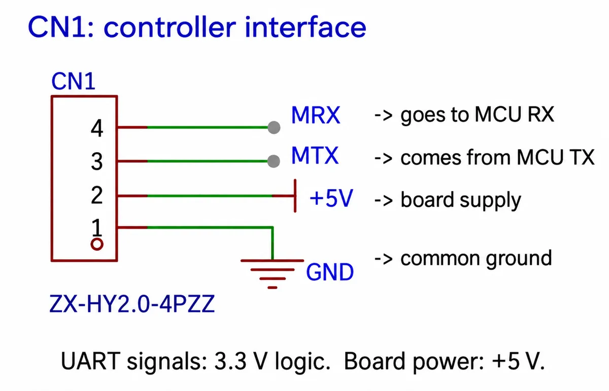
We used GP16 for the controller's transmit and GP17 for receive, with ground shared through pin 1.
The PCB antenna sits near a board edge. Keep space around it when you plan a case, then test the final placement with the intended laptop or phone. The manufacturer's distance figure is not a range measurement for an enclosed product.
Query the settings before changing them
We set UART0 to 115200 baud, 8 data bits, no parity, 1 stop bit; both ends of the serial link must agree. To configure or query the module, enter AT command mode by sending +++ with no line ending; other AT commands do use a line ending. Our driver package waited for confirmation that command mode had started, sent queries, and then returned to data mode.
Our first readout asked only for the role, operating mode, AP address, socket settings and serial settings. Skip a full configuration dump in shared logs, because it can include credentials and device identifiers. Our setup reported AP role, NORMAL mode, TCP server, AP address 192.168.1.1 and listening port 8887. Those are this setup's values, not universal ones. If your board reports something else, resolve the difference before copying any laptop settings.
Keep configuration changes, resets and factory restores out of the first run. Changing Wi-Fi settings and serial parameters at the same time makes a failed connection very hard to explain.
Join the network, then open the TCP connection
First connect the laptop to the module's AP network; ours had a name starting with EBT_. Windows showed it as an open network with no Internet. That is expected for a local link.
Then create a TCP client in a socket-testing application, with the module's AP address as the target IP and its listening port as the target port: 192.168.1.1:8887 in our case. The module's stored socket settings also showed another port; do not use it, because the laptop has to connect to the port the server is listening on. In most socket tools, creating the client entry and connecting it are separate steps, and joining Wi-Fi and opening the TCP connection are separate again. A browser's address bar is not a substitute for a raw TCP client unless you also build a web service.
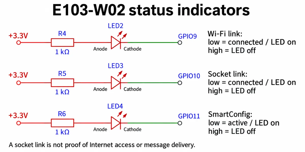
The status LEDs help tell the two steps apart. GPIO9 shows the Wi-Fi link, GPIO10 the socket connection, and GPIO11 SmartConfig activity, which is unrelated to this test. The module's user manual (V3.3) describes these states and the AP/TCP test. A network light does not confirm that a remote application received your message.
Send something recognizable in both directions
After leaving command mode, our program wrote numbered lines such as E103-W02 message 1 to the UART, and the module forwarded them to the connected client. It then waited up to 1.5 seconds for incoming bytes and paused two seconds per loop, so each cycle took more than two seconds.
Watch the laptop receive the numbered messages, then type a different, recognizable message in the client and send it back. An empty read only means no bytes arrived in that window; it does not prove the network dropped. The client will not echo anything unless you set it up to.
In our recording, the client showed the numbered messages and the RP2040 terminal later received Hello_E103_TCP_from_PC. The clip is about 48 seconds long: a short demonstration of two-way local traffic, not a long-duration or range test.
Make the local connection understandable to its user
A successful bench exchange answers the first engineering question: can these devices pass data over this local path? The next question is what the person using your prototype will do. For a workshop instrument, a dedicated laptop joining the device's network may be fine. For a phone-based product, leaving the user's normal Wi-Fi may be a noticeable interruption.
That concern has a history. In a January 2020 Arduino forum thread, a builder wanted to see boat-sensor readings on a phone without Internet and without disrupting the phone's other connectivity. Today's phones may behave differently, so test the actual devices your users carry: join, read a value, leave, and reconnect without confusion.
Before a user trial, decide whether the product should create its own network, join an existing one, or use another route for remote access. For an AP design like this one, replace the open-network demo settings with proper access control before putting real controls or private data on it. Then run the whole sequence again after a power cycle and with the enclosure in place.