
You set the brightness, choose a mode and hand your prototype to someone else. They unplug it, move it to another desk and switch it on. If everything returns to the defaults, the device can feel unfinished even when its main feature works perfectly.
Saving those choices needs a small amount of memory that survives without power. On our bench we ran the essential first test with an AT24C256 EEPROM module: write a known pattern, read it back, disconnect the power and check it again. The test also helps separate that achievable milestone from a harder promise, which is recovering correctly when power disappears halfway through a save.
Decide what the device should remember
Start with the user's expectation. A preferred volume or display brightness usually belongs to the next session. A temporary animation frame probably does not. Calibration values need more care: losing them may change what the device reports, so the startup behavior must be deliberate.
The same question appears well beyond this board. In a recent embedded-systems discussion, a developer asked how to finish saving data as power disappeared and later described a circular-record approach. Keeping the last confirmed setting, a recent checkpoint, or every last measurement are different engineering jobs. Decide which one you need first.
An external EEPROM is one option for a compact settings record. Your development board may already have suitable nonvolatile storage, so adding a module is a choice to evaluate, not a requirement. The useful part of this experiment is its test sequence, which applies to other storage methods too.
Connect the memory, then confirm its address
We used a GraftSense EEPROM module on a GraftPort-RP2040 board running MicroPython, with I2C0, SDA on GPIO 4 and SCL on GPIO 5, at 100 kHz. I2C is the two-signal connection through which the controller asks the memory to store or return bytes.
Three address switches on the module let several devices share that bus. There is a common notation trap here: the board's table lists write control bytes from 0xA0 to 0xAE, while MicroPython expects the seven-bit device address, from 0x50 to 0x57. The read/write bit is added by the I2C operation, so you do not pass 0xA0 as the address.

Our test program used 0x50, while one recorded run reported 0x52. That is a different switch configuration, not a memory that changed its address by itself. Scan the actual setup and match the result to the switches before running a write test. On a shared bus, finding an address does not prove which device is there.
from machine import I2C, Pin

i2c = I2C(0, sda=Pin(4), scl=Pin(5), freq=100_000)
print([hex(address) for address in i2c.scan()])
That is an inspection step, not settings storage. Also check the module supply, the bus pull-ups and the controller's voltage compatibility. The memory chip's permitted supply range is not permission to expose a controller's I2C pins to any voltage in that range.
Prove that one byte survives before designing a settings format
Our experiment first wrote 0xAB at memory location zero and read it back. It then wrote the sequence 0 through 127 starting at location one and read that back too. A recognizable pattern makes a mistake easier to spot than an unexplained block of numbers. Run a test like this only on a spare device or a reserved test region, because it overwrites addresses 0 through 128.
Why a short record can cross three pages
The chip holds 32,768 bytes, arranged in 512 pages of 64 bytes each. A page is a boundary the write routine must respect, not a file. You can update part of a page without rewriting the other bytes in it.
Starting the 128-byte pattern at location one leaves room for only 63 bytes in the first page. The next 64 bytes fill the second page, and the final byte goes into the third. Our driver splits the request that way and waits after each write. Sending the whole pattern as one page transaction would wrap around inside the starting page and overwrite earlier data.
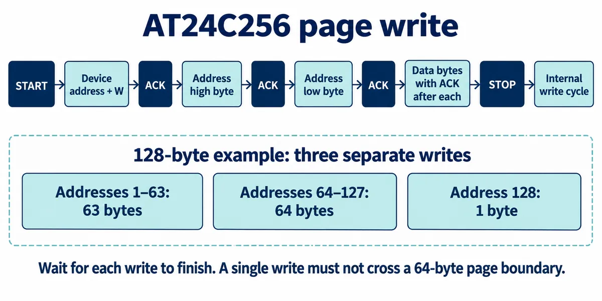
The Microchip AT24C256C data sheet is the reference for page boundaries and write completion. Our driver waits 5 ms after each write; a production implementation can instead poll for acknowledgement with a bounded timeout. Finishing the bus transfer and finishing the memory's internal write are separate events.
For this demonstration the low addresses were enough. Before using the same driver across the full memory range, its end-of-memory bounds checks need fixing: they reject a valid operation that ends at the final byte. That does not affect the small-pattern test, but it matters if the example becomes a general storage library.
Disconnect, restart, and read without writing again
A successful immediate read confirms communication. To check retention, wait for the write to finish, remove power, reconnect, and run a read-only check of the same locations. If your startup code writes the expected pattern again before checking, you have not tested whether it survived.
We did exactly that: removed device power, restored it, reconnected and ran the verification. It reported that the expected byte and pattern were retained. That supports retention after a completed write. It does not establish an endurance figure or recovery from a deliberately interrupted write.
Our test then cleared its region so it could run again. That is a lab convenience, not the behavior a settings store should have. The clearing routine wrote 129 bytes of 0xFF, which is not three complete pages despite a code comment saying so, and an EEPROM does not need a fill before every ordinary overwrite.
Turn a retained pattern into a setting a user can trust
Next, replace the pattern with a small record whose meaning is clear: a format version, the settings values and a check that can detect damage. On startup, validate the record before using it. A missing or invalid record should lead to an intentional default or a visible request to recalibrate, not a surprising output.
Choose when a change becomes permanent. Saving on an explicit confirmation, or after a short pause with no further changes, avoids writing continuously while someone drags a slider. The right policy depends on how much recent adjustment the user can afford to lose. It should also respect the memory's write endurance, without treating a manufacturer rating as a guaranteed product lifetime.
If the product must survive power loss during an update, design and test that separately. One approach to evaluate is two independently validated records: keep the old valid record while writing a new one, then pick the newest complete record at startup. Sequence numbers, integrity checks, write ordering and the exact failure behavior all have to work together. A checksum alone does not make an interrupted update recoverable.
For your next prototype review, demonstrate three situations: a normal save and restart; a restart with no valid stored settings; and power removal at different points during a save. Our experiment covers the first. The other two are acceptance tests still to run, and the values the product must remember plus what the user should see after a power cut are what define them.