
A display shows the right date while it is connected to your laptop. You move it to an exhibition stand, power it from a USB adapter, and its clock goes back to an old date. For a team preparing its first independent demonstration, this can be a surprise: the computer may have been supplying part of the product's behavior all along.
A battery-backed real-time clock (RTC) can keep counting while the main controller is off. But the chip, the backup power and the startup software have to agree on which time to trust. On our bench we tried two GraftSense RTC modules, one with a PCF8563 and one with a DS3231, on a GraftPort-RP2040 board running MicroPython. They make a practical way to understand those responsibilities before building an offline schedule or a timestamped data logger.
Separate getting the time from keeping the time
An RTC does not know today's date when it is first assembled. Something has to set it: a person, a connected computer, a trusted network time service or another suitable reference. After that, its job is to keep counting. Saving the last timestamp in ordinary nonvolatile memory preserves a number, but it does not advance during the hours the device was unplugged.
That distinction still trips up current projects. An October 2, 2026 MeshCore discussion asks about adding an RTC to a XIAO radio kit without GPS. One reply reports persistence on a different setup, which does not establish compatibility with the proposed kit. The transferable question is what source of time an independent device can rely on.
A MicroPython discussion from May 2023 shows another trap: correct time in Thonny and wrong time when running on its own. The exchange pointed to the computer's time update, and a participant later found a tuple-passing mistake. A working desktop session is a useful first test, but it does not replace the way your customer will actually power and start the device.
What the two module experiments showed
Both modules connect over I2C, SDA on GPIO 4 and SCL on GPIO 5. Our examples scanned the bus first: the PCF8563 answered at seven-bit address 0x51, the DS3231 at 0x68.
The PCF8563 test read and changed time fields, loaded a fixed demonstration date, configured the clock output and set alarms. The terminal then showed the seconds advancing. Those are useful checks of communication and calendar access.
Look closely at the alarm section, though: all five checks said the alarm had not triggered. The program set the clock to 18:00 and the daily alarm to 10:30, then waited five seconds. That output confirms the configuration calls ran; it is not an observed alarm event. A printed message about configuring a 1 Hz output likewise does not replace a measurement at the output pin.
The DS3231 test set the time, read it back, printed the internal temperature (26.25 °C) and status, and repeatedly read time and alarm flags. The seconds advanced from 16 to 18 and the alarm flags stayed false. Neither test included a timed main-power-off run or a long-term drift comparison between the two modules.
Choose for the time error your product can tolerate
For a simple display or reminder, the main requirement may be a sensible time after an overnight power interruption. For records collected over weeks without synchronization, accumulated error matters more. Define the tolerance in seconds or minutes over the real offline period before comparing clock specifications.
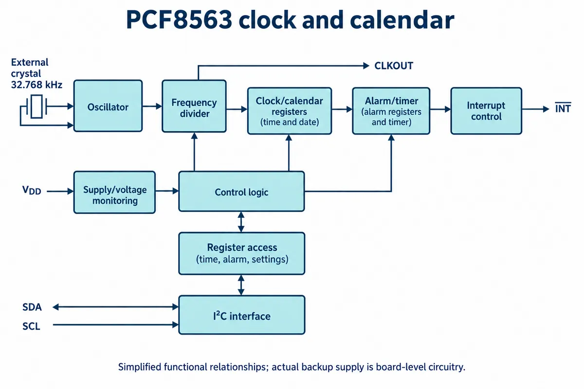
The PCF8563 module uses an external 32.768 kHz crystal. Its result depends on the crystal, its loading, temperature and the completed board, and typical-curve plots do not prove a month's accuracy for an assembled module. The PCF8563-labeled part on our module came with a reference from a supplier other than NXP, so confirm the fitted device and its own specification when you reproduce the design.
The DS3231 integrates a temperature-compensated oscillator. Analog Devices specifies ±2 ppm from 0 °C to 40 °C, with wider limits over the full temperature range. As a scale illustration, a constant 2 ppm error adds up to about 5.2 seconds in 30 days (2 × 10⁻⁶ × 30 × 24 × 3600). That is arithmetic, not a measured monthly result for our board, and the initial setting error still adds to it.
Neither choice removes the need to test backup power. On the PCF8563 module, diodes feed the clock from either the main rail or the coin cell. The DS3231 module connects the cell to the chip's dedicated VBAT input. Both boards also carry regulators and other circuitry, so a chip's standby-current figure is not the module's battery life.
Change the startup behavior before testing retention
Both of our test programs wrote the controller's current time into the external RTC on startup. That is convenient for exercising the interface. It is the wrong default for a product: an unsynchronized controller can start with an old date and overwrite a correctly running external clock.
In a deployed prototype, read the RTC and its validity indication first. Set it only when commissioning the device, when the stored time is untrustworthy, or when you deliberately synchronize to a better reference. Also decide whether the stored calendar is UTC or local time; the hardware does not implement your time-zone and daylight-saving policy.
Check the validity flag before trusting a plausible-looking date. The PCF8563 has a voltage-low flag; the DS3231 has an oscillator-stop flag. A set flag means the application must investigate or establish time again. A clear flag does not prove anyone entered the correct date in the first place. NXP's PCF8563 data sheet and the DS3231 data sheet describe what each flag means.
Our DS3231 run printed status 0x88, which includes the oscillator-stop flag, and the driver did not clear it when setting the time. A successful time read-back and a finished validity-handling policy are separate milestones. Here is a read-only check of both flags that does not change either clock:
from machine import I2C, Pin

i2c = I2C(0, sda=Pin(4), scl=Pin(5), freq=100_000)
addresses = i2c.scan()

if 0x51 in addresses:
    seconds_register = i2c.readfrom_mem(0x51, 0x02, 1)[0]
    print("PCF8563 voltage-low flag:", bool(seconds_register & 0x80))

if 0x68 in addresses:
    status_register = i2c.readfrom_mem(0x68, 0x0F, 1)[0]
    print("DS3231 oscillator-stop flag:", bool(status_register & 0x80))
We checked this against the documented registers but have not run it on our hardware. Confirm that a PCF8563-compatible part uses the same register map. A full application also has to read calendar values consistently, validate them and handle I2C errors. Our PCF8563 driver reads fields one at a time, so a rollover can happen between reads, and the DS3231 driver's 12-hour decoding and alarm-writing paths need fixing before those modes are relied on.
Test the product's restart, not just the clock chip
Set a known correct time once. Disconnect the programming environment, remove main power for a measured interval while leaving the intended backup supply connected, then restore power through the product's normal supply. Read the clock before any synchronization code runs. Compare it with your reference and record the validity flags as well as the displayed date.
Repeat with the backup source missing or exhausted. Your display or logger should recognize an untrusted clock rather than silently stamping new records with confident-looking times. Also try crossing midnight: checking only the seconds can miss calendar or tuple-conversion errors.
For a scheduled action, test an actual trigger at a nearby future time. The four-pin module connection we used carries power, ground, SDA and SCL; it does not route an alarm output to a controller wake pin. Polling an alarm flag and waking a sleeping controller are different integration jobs, and the DS3231 alarm flag also has to be cleared after each event.
These tests let a small team make a concrete promise: how the device gets its initial time, how long it must run offline, what happens after a power interruption, and how it behaves when the time is no longer trustworthy. The expected offline period and the acceptable time error are the two numbers that make the clock, power and firmware decisions clear. We have not yet run these restart tests on our modules.