
You want your prototype to notice when a surface gets warmer, but attaching a probe to that surface is awkward. Perhaps the object moves, must stay removable, or cannot have a cable stuck to it. A non-contact infrared sensor looks appealing: point it at the part and read a temperature.
Getting a number is the first milestone. Getting a number that represents the intended surface depends on the target, the distance and the sensor's position in the enclosure, and those choices have to be made together.
On our bench we connected an MLX90614 infrared sensor on a GraftSense carrier to a Raspberry Pi Pico running MicroPython, read live temperatures and held a finger close to the sensor. Here is what that showed, and what it does not establish for a product that watches one fixed surface.
Start with the two temperatures in the readout
The MLX90614 combines an infrared detector and signal processing in a metal can. Its object temperature is derived from the infrared energy it receives. The value our driver called "ambient" is the sensor's own temperature, not an air probe placed near the target.
That matters inside an enclosure. If the circuit board warms up, the sensor and the surrounding air may not match. If your application needs room temperature as well as the surface reading, do not assume these two outputs are two independently placed measurements.
The carrier's schematic specifies an MLX90614ESF-BAA, a regulator and I2C pull-ups on a nominal 3.3 V rail, separate from the board's power input. Check the actual sensor variant and board revision before using a different supply or another carrier's wiring diagram.
The connection and reading test
We used the Pico's I2C0 connector with GP4 as SDA and GP5 as SCL, plus power and ground, at 100 kHz. Some documentation for this carrier mentioned a different address and a 1 MHz interface; ignore that for this setup. The usual default address for this device is 0x5A, but confirm it on your module. A successful scan proves communication with something at that address, not calibrated accuracy.
Our test program read the sensor several ways: through internal helpers, through properties and through a method returning a dictionary. Each route reads the device again in sequence. Agreement between them checks the software interface; it is not several thermometers confirming one result. The driver also read two data bytes without checking the packet error code that the protocol provides, so a product implementation needs extra communication checks and handling for invalid readings.
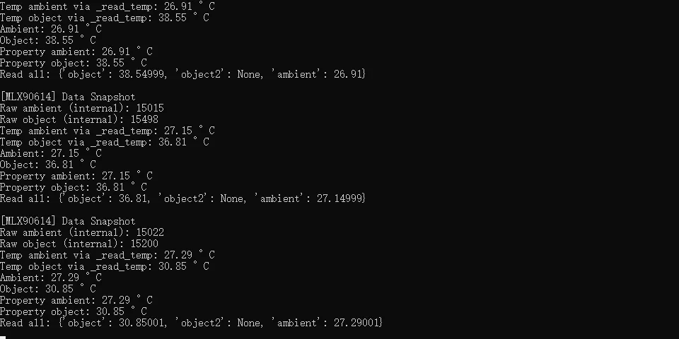
The object readings were 38.55 °C, 36.81 °C and 30.85 °C, with sensor temperatures near 27 °C. The output also showed object2: None, so this is a single-zone sensor. We had no measured gap and no calibrated reference target, so this is a response demonstration. It does not establish clinical accuracy, and the BAA variant on this carrier is not a medical-grade part. We are using the test to understand surface sensing, not anyone's body temperature.
A sensor does not read a single point
A long-running Arduino forum thread from 2012 starts with a familiar problem: temperatures appear on the serial monitor, but the reading becomes implausible as the target moves farther away. The distance in that user's setup is not a universal range limit. The useful question is how much of the sensor's view the target fills.
At a greater distance, a small part fills less of the view and the surrounding scene contributes more. Moving the sensor closer or choosing a different optical variant may help, but the part number and the geometry have to be checked together. Do not correct a changing background contribution with a constant offset until one reading looks right.
Melexis defines field of view with an angular sensitivity profile. The MLX90614 data sheet explains that the nominal field-of-view boundary is not a hard cutoff. Use it to plan the arrangement, then verify it with the actual target. A narrow-looking opening in an enclosure is not automatically a useful optical design.
The enclosure and the surface become part of the measurement
The same data sheet's application notes describe errors when an enclosure opening enters the sensor's view. The housing emits infrared energy too, so a sensor recessed behind a thick front wall can behave differently from the same sensor on an open bench. Test the final recess and opening before settling the mechanical design.
A clear cover has to be checked at the infrared wavelengths involved. Visible transparency is not enough: ordinary glass is generally opaque in the band this sensor uses. A shiny metal target is also different from most surfaces. When a surface has low emissivity, meaning it emits thermal radiation poorly, reflected surroundings can contribute strongly to the reading.
Define the application before adjusting numbers. A stable dark-coated reference target, a polished metal part and a removable object that moves are different conditions. Changing an emissivity setting cannot remove every effect of background, reflection or mounting. If a setting needs changing, follow the manufacturer's procedure and record the actual target surface.
When reading the package pinout, note that the manufacturer drawing is a bottom view; do not mirror it by accident when looking from above. The metal case connects to VSS.
Make the next test representative of your product
For a fixed surface-monitoring prototype, hold the target position steady and compare the reading with a suitable reference measurement under controlled conditions. Record target material, surface finish, distance, angle and sensor warm-up, then change one condition at a time. That shows whether a difference follows the target or the measurement arrangement.
After the open-bench check, install the sensor in the intended enclosure and repeat the test with nearby electronics powered as they will be in use. Check whether moving the removable object, warming the board or changing the background produces a change large enough to alter the decision your product makes.
Decide what the application should do with an unavailable, implausible or stale reading. A display can mark missing data instead of showing the last value as current. A temperature-triggered action needs an explicit response to measurement failure. We have not built that behavior yet.
Non-contact sensing is useful when a surface can stay in a well-defined view and a contact probe is impractical. If the target is tiny, its position changes widely, or the opening cannot accommodate the optical path, a different sensing arrangement may be easier to validate. Make that choice before polishing the display or designing a bracket around a misleading bench result.