
Your sensor works on the desk. Now it needs to send a reading from a greenhouse, workshop or outdoor installation to a receiver somewhere else. You do not need a video stream or a browser on the sensor. You need a few bytes to arrive often enough that the person looking at the display can trust what it says.
A low-data-rate radio is worth investigating, and the first question is what counts as a successful update: the transmitter accepted the message, the receiver got it, or the application recognized it and updated the display. Those are three different events.
We tried two routes on our bench. One used a pair of HC-14 modules as a transparent serial link. The other used an Ebyte E22-900M22S radio on a carrier with its own RP2040-Zero, which gives an external controller explicit commands for sending and receiving packets. These were separate paired-radio tests; the HC-14 and the E22 were not talking to each other.
Start with the message your product needs
Imagine a remote display showing a workshop's temperature. A missed reading may be tolerable if another arrives soon and the display shows when the last update came in. A button commanding a machine to change state is different: the operator needs to know whether the command was acted on, and a repeated command must not repeat the action. Decide which case you are building before selecting the module.
Write down four things for your prototype: the message size, how often it must arrive, how old a reading may get before it misleads, and what the receiver should do when communication stops. Even rough answers make the first radio test much more useful.
Route one: replace a serial cable with an HC-14 pair
The HC-14 contains its own controller. Once configured, bytes written to one module's serial input are transmitted and come out of the other module's serial output. This is transparent serial: the host does not issue a radio command per payload. It still has to decide where one application message ends and the next begins.
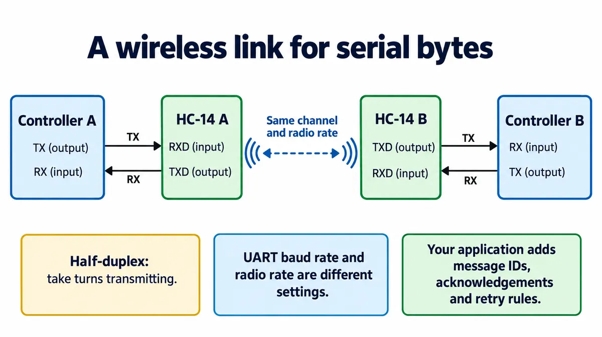
The radio is half-duplex, so the two ends take turns, and both modules need matching radio settings. The serial baud rate describes the local link between controller and module; the radio rate describes a different part of the journey. Raising the serial baud rate alone does not make the wireless link faster or more reliable.
We connected both modules to one Raspberry Pi Pico on separate ports, UART0 on GP16/GP17 and UART1 on GP8/GP9, both at 9600 baud, so we could configure both and watch a payload come back through the other port.
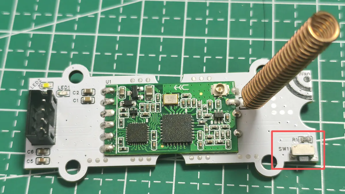
The module can use its small coaxial connector or a soldered spring antenna; the manufacturer's manual says to choose one, not both. Before copying the wiring, resolve one electrical detail. The carrier runs the module from 5 V, and the HC-14 manual describes the UART high level as following the supply voltage. That is not enough to connect a 5 V-powered HC-14 directly to a 3.3 V controller. Check the actual module revision and signal levels, and add level conversion where needed. The manual also calls pin 7 NC in its table and WKUP in an example; our carrier leaves it unconnected.
Configure first, then release the button
We checked communication, set channel, rate and transmit power, read the settings back, then released configuration mode for the data test. An OK here proves a local serial conversation with the module. It does not prove that the other radio can hear it.
Both modules reported rate 7, +20 dBm, channel 7 and 9600 baud. In this manual, channel 7 maps to 419.36 MHz; it is not shorthand for 433 MHz. Choose frequency, power and antennas for your hardware and the rules where the product will operate.
Read the timing results carefully
At rate 1, an 80-byte test arrived in two chunks, printed at about 5,005 ms and 10,010 ms (the second figure is cumulative). A 500-byte test at rate 7 printed 4,002 ms; a 500-byte random payload at rate 8 printed 3,434 ms. These came from different runs with different payloads and settings, so they are not a controlled benchmark.
Software time is also inside those numbers. The receive function in the HC-14 driver we used (by ben0i0d, under a noncommercial Creative Commons license, so not usable as-is in a commercial product) waits for a quiet interval, 2,300 ms by default, before returning buffered data. The test started its clock after the send call. The printed interval is not time over the air.
For a product, make the message boundary explicit with a length field or a suitable delimiter, and count complete messages. Otherwise a pause between radio chunks may look like the end of a message, or several readings may arrive in one read.
Route two: give the application explicit packet commands
The bare E22-900M22S uses SPI, not a transparent UART. On this carrier an onboard RP2040-Zero runs the radio driver and translates UART requests from an external controller. Each end therefore has an external controller, the carrier's controller and the radio. The bridge firmware's radio code carries MIT notices crediting E H Ong's micropySX126X and Jan Gromes's RadioLib.
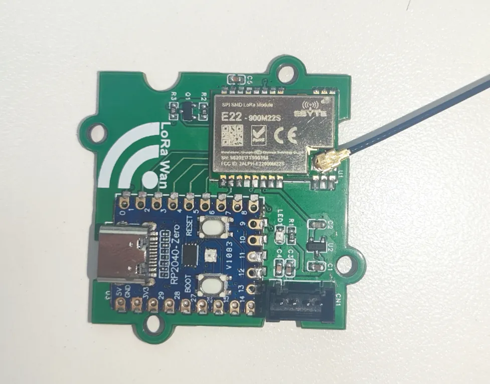
The carrier makes a 3.3 V radio supply from its 5 V input and controls transmit/receive switching. The software exposes ping, initialize, send, receive and status calls through a newline-delimited JSON protocol. Received packets include RSSI and SNR, which hint at signal conditions but do not replace checking the payload and counting missing messages.
There was a version mismatch to resolve: the carrier CAD labeled GP9 as STX and GP13 as SRX, while the later bridge program used GP8 TX and GP9 RX. Identify the board and firmware pair you actually have, then trace host TX to the bridge's RX and back. The host link runs at 115200 baud with 3.3 V logic.
Check the receiver, not just the send return value
We used 915 MHz and 0 dBm for short-distance bench testing, started the receiver first, then sent numbered messages and checked them in order. One recording ended with 20 messages received; a second, with roles swapped, also reached 20. Both directions were observed, which is stronger than a transmitter printing "sent." It is still a small bench test, with no recorded separation distance, enclosure comparison or long packet-loss log.
The meanings of the responses matter. A ping checks the local UART bridge. A successful send reports completion on the transmitting side. Neither is an acknowledgment from the remote application. If the product needs that confirmation, design a reply carrying the message ID and check it before telling the user an action succeeded.
Choose the amount of control you need
The HC-14 route suits a simple serial radio pair, if you build message handling around the byte stream. The E22 carrier adds packet-level control and diagnostics, plus firmware on another controller to install and maintain.
Neither test establishes LoRaWAN or Meshtastic compatibility. LoRaWAN adds end devices, gateways and a network server, as the LoRa Alliance describes. Two boards exchanging short messages, even with "LoRa Wan" printed on a carrier, do not demonstrate that network software.
Turn a working link into a useful prototype test
Change one condition at a time. Send the real message at the intended interval, log its ID at both ends, and record late, missing and duplicate messages. Repeat with the case fitted, at the intended location, with the real antenna and mounting, and after power-cycling either end. Do not turn the largest distance in a module brochure into the range of your assembled product.
For a remote reading, show its age and a clear stale-data state. For a command, define the acknowledgment and what happens when it does not arrive. If a command is retried, the receiver should recognize the repeated ID and not apply the action twice. That gives the user a clear outcome instead of a light that only means bytes left the serial port.