
One temperature reading is easy to understand. Add a second probe near the power supply and a third beside the air inlet, and the questions change: which number belongs to which location, how much extra wiring will fit, and what happens when someone unplugs a probe?
If you already have a working development-board prototype, a shared 1-Wire bus is a useful way to explore those questions. Several compatible sensors share one data connection, and their individual addresses let the software tell them apart. The part that needs care is moving from a sensor on the desk to the real cables, power supply and physical locations in your product.
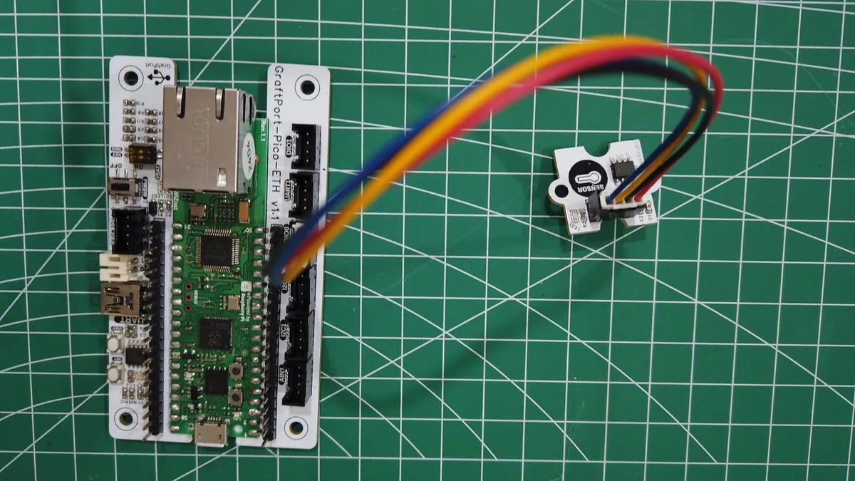
On our bench we connected a single GraftSense temperature module to a GraftPort-Pico-ETH board running MicroPython, read it, and recorded the output. The demonstrated setup has one probe. This note covers what it showed and what to check before adding more.
Start with the connection, not the sensor count
"1-Wire" describes the data interface. It does not mean the assembly needs only one physical wire: the devices still need ground, and an externally powered sensor needs a supply. The bus is shared, so one device pulling the data line low affects every device on it.
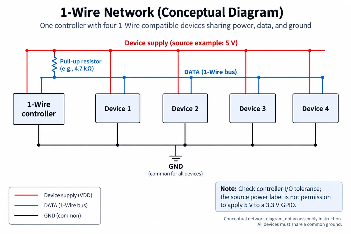
That shared line is why compatible devices need addresses, and why simply joining every pin labeled DATA will not work. A DHT11 temperature-and-humidity module, for example, uses a different protocol entirely.
We connected the module to GPIO14, VBUS and GND. Treat that as a record of this module and carrier, not a wiring prescription for a bare sensor. Before copying it, check the module's fitted part, its pull-up resistor and the voltage that actually reaches the controller's data pin. A module powered from VBUS does not make its data output safe for every controller.
External power is the easier place to start, because it separates the sensor's supply from its data line. Parasite-powered versions draw energy from the data line and have extra requirements during conversion.
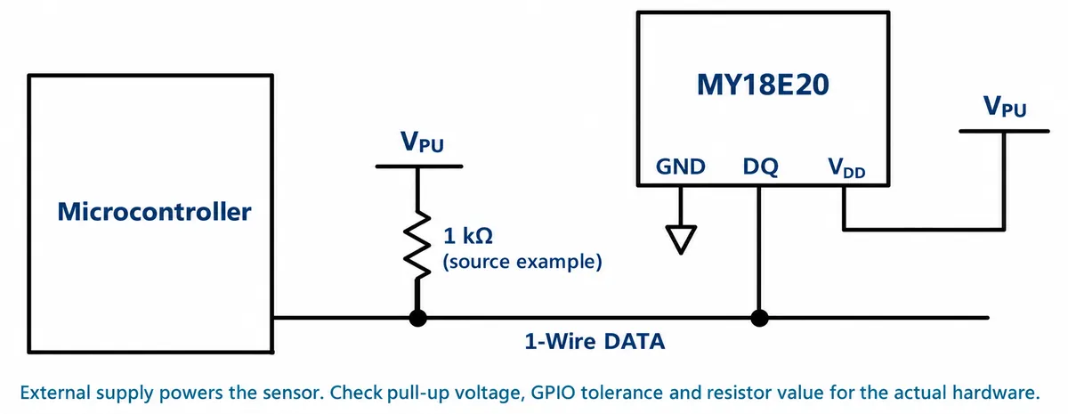
One naming detail matters here. Our module documentation describes an MY18E20 part, while some references and code messages say DS18B20. The software interface is similar, but electrical limits and conversion times are not automatically interchangeable. Identify the actual component before choosing those values.
Scan first, then give each probe a location
MicroPython's standard onewire and ds18x20 modules provide the basic calls:
from machine import Pin
import onewire, ds18x20

ds = ds18x20.DS18X20(onewire.OneWire(Pin(14)))
roms = ds.scan()
print(roms)
The scan returns device identifiers, usually called ROM addresses. Our driver also filters for the sensor families it knows how to read (family codes 0x10, 0x22 and 0x28). An empty result is a reason to check power, wiring and device compatibility before touching the display or enclosure.
With one probe, the address looks like unnecessary detail. With several, it is the link between a physical location and a reading. A practical setup step is to connect probes one at a time, record each identifier and give it a label such as "air inlet" or "controller compartment." Keep that mapping separate from the order in which a scan happens to return devices.
This is a real pitfall. In a September 2015 Arduino discussion, a builder using fixed sensor addresses found another library call was overwriting them. Check what an address-handling function actually does, and verify the displayed location after reconnecting or replacing a sensor.
Ask for a conversion, wait, then read
A temperature sensor does not have a fresh measurement the instant the controller asks. Our loop started a conversion, waited, read each stored address and then started the next conversion. Compatible sensors can convert together, after which the controller reads each result.
Our loop waited 500 ms. For a DS18B20 at 12-bit resolution, the DS18B20 datasheet gives a maximum conversion time of 750 ms. Use the timing for your actual part and resolution; a faster polling loop does not produce fresher measurements.
Reading a result means selecting one address, receiving the sensor's scratchpad registers and checking a CRC. That check detects a damaged message; it says nothing about whether the probe is measuring the temperature you care about.
The error path matters for a product interface. Our driver's read call can return None after a failed check. Displaying that as zero degrees turns a communication failure into a believable measurement. On a screen or in a log, distinguish "no current reading" from a real number, and decide whether an older value may stay visible with a clear stale-data marker.
What our bench test shows
We held the sensor gently while watching the terminal. The output repeated the same ROM identifier with readings from about 32.6°C to 34.5°C. That shows the program obtains changing values from the sensor. It does not establish accuracy, response time or multi-probe reliability.
For an enclosure experiment, repeat this first with one clearly labeled probe, then put it where the measurement makes sense. A probe touching a warm component, one in moving air and one pressed against the enclosure wall answer different questions, even with identical code. Add the second location only once the first measurement is understandable; otherwise several plausible numbers just make an unclear experiment look more convincing.
We also ran a DHT11 module on GPIO13 as a separate experiment. It looks similar on the bench but reads temperature and humidity from a timed pulse message, with no ROM address. Its readings changed when warmed, but there was no reference instrument, so that was a response demonstration, not a calibration. If you need temperature at several locations, an addressed bus may fit. If you need humidity at one location, a different sensor may suit better. "Fewer wires" alone is not enough to choose.
Add the real harness before trusting the extra readings
The next risk appears when cables replace short bench connections. In a June 2019 Arduino thread, a builder's five probes used branches of different lengths, and adding probes stopped the readings. A resistor change restored detection, but an abnormal temperature remained; the thread does not show a complete fix.
That is a reason to test your cable layout early, not to copy one resistor value. Analog Devices' guidelines for reliable long-line 1-Wire networks explain how cable loading, branch layout and power arrangement affect communication. Its cable and driver assumptions are not a distance guarantee for a Pico GPIO.
For the next build, record the cable layout alongside the sensor IDs. Add one branch at a time, confirm every expected address stays detectable, and compare readings with a reference suited to the experiment. Include a restart and a disconnected probe; those are the moments when a tidy bench display becomes confusing to someone using the prototype.
If the shared bus is hard to validate in the intended enclosure or harness, reconsider the arrangement before polishing the display. Fewer branches, shorter connections or a different interface may fit better. That choice depends on the physical product, not just the number of spare GPIO pins.