
Your sensor works beside the development board. Now the enclosure design puts it at the far end of an exhibit, next to a machine, or in a separate outdoor housing. Extending the jumper wires is the obvious first thought. Before ordering a longer cable, you need to know what will carry the data and what happens when the two ends run from different power supplies.
RS-485 is one way to make that connection. A converter turns the controller's short-range logic signals into a differential signal on a pair of wires. It does not make your sensor understand commands, provide power at the far end, or prove that the finished installation will work. Those are separate parts of the design.
On our bench we connected a GraftPort-RP2040 board to a computer through a GraftSense TTL-to-RS-485 module and a USB-to-RS-485 adapter, and exchanged text in both directions. Here is what that showed, and how to use it to plan a remote-sensor prototype.
Start with the interface your sensor actually has
If the sensor already has an RS-485 port, get its communication manual as well as its wiring diagram. You need the command that requests a reading, the address that identifies the sensor, and how the reply is encoded. "RS-485" on two products does not mean they speak the same application protocol.
If the sensor only has a UART, a converter at each end may be part of the answer. An I2C sensor needs more interface work; this converter is not an I2C cable extender. One option for a room-monitoring prototype is a small controller beside the sensor that reads it locally and sends measurements over the long link. We have not tested that architecture.
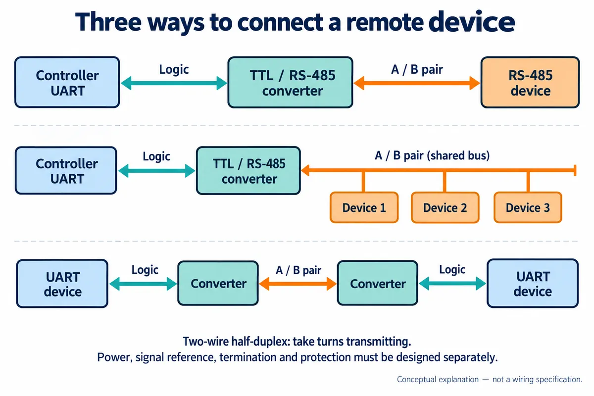
Keep the software question apart from the cable question. A request such as "read sensor 2" belongs to a protocol the devices implement; the RS-485 connection just carries the bytes. Texas Instruments' RS-485 Design Guide makes the same distinction.
What our bench setup contained
The GraftSense carrier holds a small TTL-to-RS-485 submodule (a JSM485ESA transceiver), connects it to the board's UART connector and brings the bus out to terminals. A USB-to-RS-485 adapter connected the bus to a PC.
On this carrier, MTX means the microcontroller's transmit, so it goes to the board's TX pin, and MRX goes to RX. Many generic converters label pins from their own side, which needs TX-to-RX wiring instead. Follow the signal direction rather than applying one naming rule to every product.
| Connection | Destination |
|---|---|
| GraftPort GPIO 8, UART1 TX | Carrier MTX |
| GraftPort GPIO 9, UART1 RX | Carrier MRX |
| Module RS-485 A | Adapter T/R+ |
| Module RS-485 B | Adapter T/R− |
We also connected ground to the adapter. Treat that as a record of this bench test, not a grounding rule for every installation. The carrier artwork uses GND and PGND in different views, and its front and back disagree on the sign of the B terminal; check the actual module and adapter documentation before applying power.
The word "isolated" in a product title is another reason to read the documentation. A transceiver chip's specification does not set the isolation rating of a complete converter, and the carrier schematic shows the purchased converter only as a block. We could not verify its isolation barrier or surge performance, which matter if the sensor and controller end up at different ground potentials.
Make the short connection understandable first
On the PC, open the adapter's serial port at 9600 baud, 8 data bits, no parity, 1 stop bit, choosing the port that belongs to your adapter and the driver for its USB chip.
Our test program opened UART1 on GPIO 8 and 9 at 9600 baud, sent a numbered text message, waited 100 ms, printed anything received, and repeated every two seconds. There was no separate direction-control pin in this setup, so it is not a drop-in test for a bare transceiver that needs explicit driver-enable control.
The PC received the numbered messages. On several loops the microcontroller printed Received: test, matching text typed manually on the PC; on others it printed No data. That is evidence of bytes moving both ways over a short bench link.
It is not an automated loopback test: the program never compared received bytes with what it sent. And No data only means nothing was waiting at that moment, which is expected when the other end is a person who has not pressed Send. A manual terminal is good for first checks, not a substitute for the sensor's real reply behavior.
Turn the bench test into a sensor conversation
Next, replace the typed text with the sensor's documented request and response. Record the exact bytes sent, the expected reply length or framing rule, and the time allowed for a reply. Parse binary replies as bytes; decoding them as UTF-8 text, as our test did, only suits text messages.
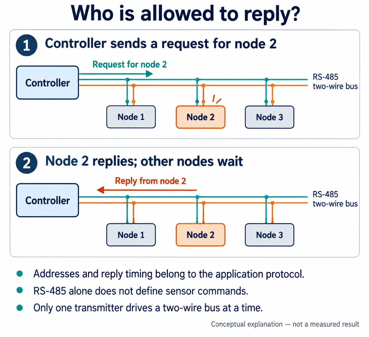
Connecting several modules to one pair does not add that coordination. For the first sensor test, keep a single sensor on the bus and confirm a known reading or status reply. Then disconnect it on purpose and check that the application reports a missing device rather than showing an old value as current. Add a second sensor only once you can tell those two outcomes apart.
Then test the cable route and power arrangement
The next prototype should use the planned cable, connectors and power supplies, because a working USB bench setup can hide installation problems. In a 2015 Arduino discussion, a building-automation developer described a link that worked on a separate supply but failed once connected to the installed system's power.
Differential signaling helps with noise common to both wires; it does not make the allowable voltage between devices unlimited. Treat signal reference, cable shield, protective earth and isolation as separate questions. "Use one ground point" is not a complete plan for a system with several supplies, USB connections and grounded equipment.
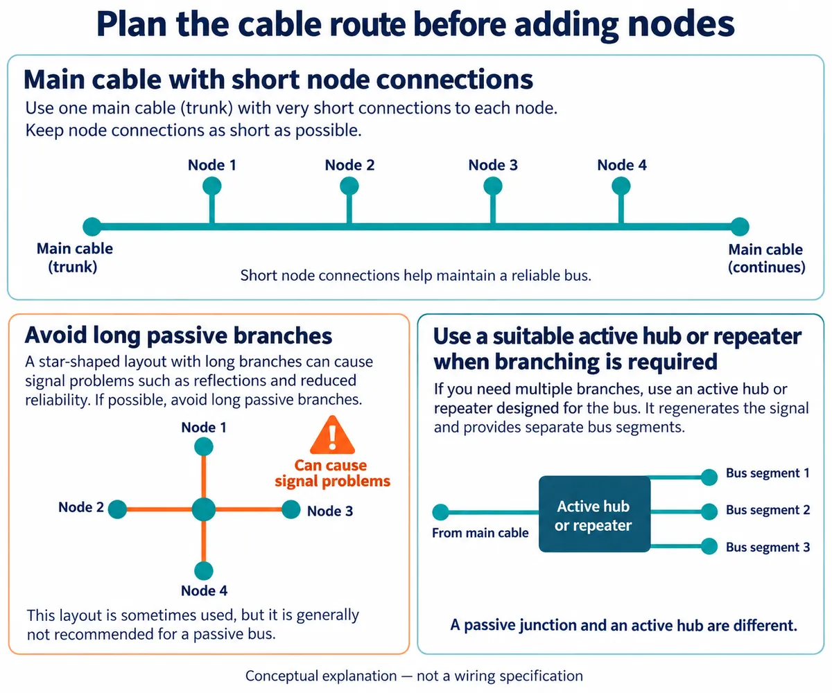
Route the cable away from likely interference sources where practical, and test while nearby motors or other loads run as they will in use.
Termination is part of the cable design too. Our submodule carries a 120 Ω termination resistor. Not every module on a multi-device bus should have termination enabled; it belongs at the actual cable ends. Whether a short link needs it at all depends on signal edge speed and cable delay, not just baud rate, as TI's termination article explains.
During the longer-cable test, log missing and malformed replies, restarts and recovery after reconnecting a device. Record cable length, supply arrangement, baud rate and which termination resistors are fitted. That gives the team a repeatable setup to compare changes against, rather than "it worked yesterday." Our short bench run produced no long-cable error-rate data, so it cannot set those acceptance limits for you.
A remote-sensor prototype is ready for its next iteration when you know how the far end is powered, how a valid reading is recognized and how the system behaves when the link fails. Those choices drive firmware, connectors, enclosure openings and installation instructions; the converter is only one part of the work.