
You have a controller that can blink an LED. Now you want it to start a small motor in a moving display, a model, or a hands-on exhibit. A switch module seems like the missing piece: connect a control pin, call on(), and let the motor run. Before choosing one, though, you need to know where it interrupts the motor's circuit, and whether that arrangement fits the rest of your prototype.
On our bench we used a GraftSense module built around a JMSL0406 MOSFET, driven from a GraftPort-RP2040 controller board running MicroPython, to start and stop a small motor with a wheel attached. Here is what that test showed, and what you would need to establish before using the same approach in your own assembly.
Start with the connection your load needs
A low-side switch interrupts the return path from a load toward supply ground. A high-side switch interrupts the supply path into the load. That difference matters when your motor or other load is already connected to ground elsewhere: opening one return wire may not interrupt the whole circuit.
This is a practical integration question, not just terminology. An AskElectronics discussion from August 2023 asks about using a MOSFET module with a permanently grounded load. It shows why the existing connections should be part of module selection. It says nothing about whether this particular module suits that poster's hardware.
On this module, the control connector and the two-position load terminal have different jobs. The controller sends an instruction through DAT. The load terminal belongs to the external load circuit; it is not a powered output socket.
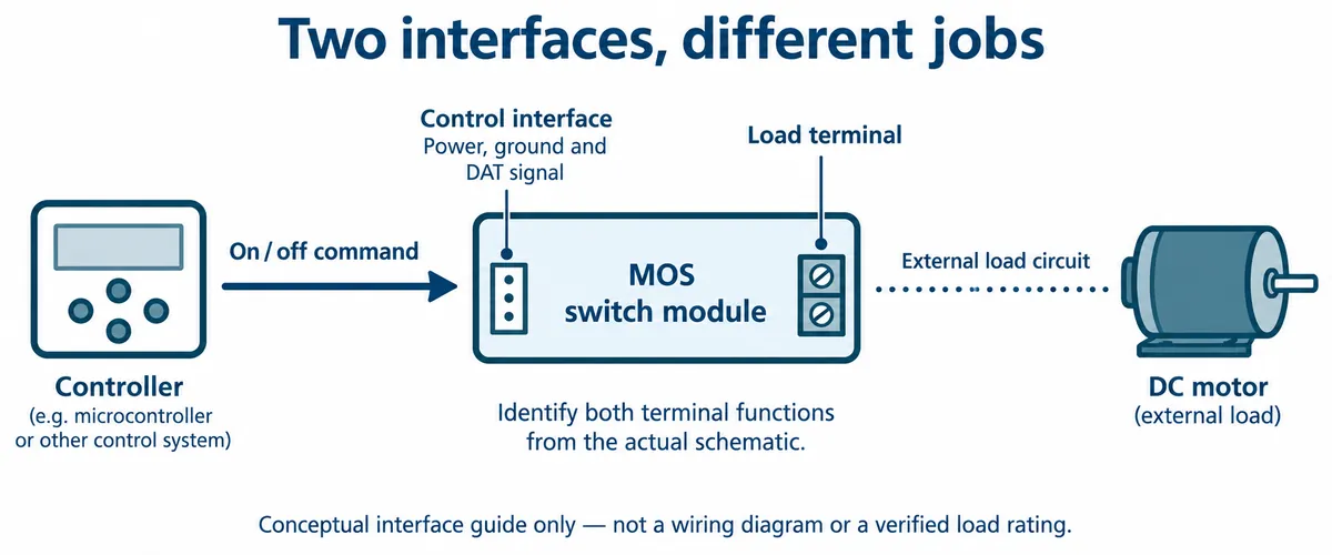
Check the actual switch circuit
The module schematic identifies an N-channel JMSL0406AG MOSFET as Q3. Its drain goes to terminal 1; its source and terminal 2 connect to AGND. That is a low-side switching arrangement. The control path passes through Q2, a PC817 optocoupler and Q1 before driving the MOSFET gate, the input that controls conduction.
Watch for documentation that disagrees with the board. Some explanatory material for this module showed a mechanical relay coil and contacts, which is not the MOS circuit in the schematic, and the driver package we used is called relay_driver. Neither name nor drawing turns this into a relay. Work from the schematic.
The schematic also connects GND and AGND through a 1-ohm resistor (R6). So the optocoupler does not make the board electrically isolated. If your project depends on keeping circuits separate, that connection is part of the decision, not a detail to infer from the optocoupler's name or rating.
The schematic supports an explanation of the switching path. It does not resolve every difference between wiring notes, illustrations and the physical board revision. Confirm the actual terminal mapping on your board before wiring a load.
The bench test
We used the controller's DIO1 connector, with GP14 as the control signal and GP15 unused. The software was relay_driver version 1.0.0 in its normal mode. In that driver, initialization makes the control pin an output and sets it low; on() sets the pin high and off() sets it low. Keep a copy of the exact package with the main program: a similarly named driver or a later revision may not behave the same way. (The archived library also carried an internal 0.1.0 version string, another reason to keep the files themselves.)
The executed sequence was short:
- Initialize the normal-mode switch on GP14.
- Wait three seconds during startup.
- Call
on()and print the on-state message. - Wait five seconds.
- Call
off()and print the off-state message.
The five-second interval comes from the program's sleep(5) call; an older comment said one second, so trust the statement, not the comment. The file also defined a music routine that the main sequence never called. This test supports an on/off demonstration, not music or PWM speed control.
On the bench, the wheel was at rest, moved, and came to rest again. That is more informative than terminal messages alone. It does not give a measured speed, starting current, load torque or endurance result.
Carry one more distinction into your software. In this driver, get_state() reads the control pin. An "on" result means the output command is high; it is not feedback that the motor is turning. A disconnected motor would leave the same state. If movement matters to the product, decide how you will observe it: during a bench test, or through a separate sensor in the eventual design.
A component rating is not a tested module rating
Once the wheel moves, the next question is often whether the board can run a larger motor. The JMSL0406AG datasheet lists a 40 V drain-to-source absolute maximum and a 70 A continuous drain-current rating at a specified 25°C case temperature. Those are component limits with conditions. Our test does not show a whole module, connector, wire set and enclosure operating anywhere near those values.
The same care applies to the control voltage. A MOSFET's threshold voltage marks the beginning of conduction, not a promise that it can carry the intended load with low resistance; the manufacturer's on-resistance conditions are more relevant. Texas Instruments explains this distinction in a November 2024 MOSFET application note. On this module, the intermediate driver circuit also means that controller-pin voltage and MOSFET gate voltage are different quantities.
We also have two USB power-meter readings from the setup, about 4.87 V / 0.019 A / 0.09 W and 4.86 V / 0.031 A / 0.15 W. Without a clearly identified measurement point and load condition, they cannot tell you the motor's input power, the MOSFET's loss, or the efficiency of the assembly. Do not size a motor supply or a board load limit from them.
Turn the demonstration into a useful integration test
For a moving exhibit or another small prototype, the next step is to repeat the on/off sequence with the actual load and its intended supply. Before doing so, establish the terminal functions, the load's starting and running requirements, and the protection that load needs. Keep any existing ground connections in the drawing; leaving them out can change whether the switch controls the device at all.
Then record what our wheel test does not answer:
- whether motor startup disturbs the controller;
- what happens to the output when the program restarts;
- whether the motor responds reliably over many cycles;
- how the assembly behaves over its intended operating cycle, including temperature.
Those results tell you whether to keep this module, change the switching arrangement, or move to a different driver design. Our test gets you to the first milestone: a software command and a visible motor response.