
Your prototype works with two buttons. Then someone tries it and asks for a separate Start button, a mode selector and a light that shows whether it is ready. The interface gets better, but the development board runs out of spare pins. Do you need a different controller, or can you keep the work you have already done?
An I/O expander can help with ordinary switches and indicators. It gives the controller another set of digital connections over a shared bus. The useful starting point is one dependable interaction (press this switch, change that light) before laying out the whole panel.
On our bench we tried two expanders on GraftSense carriers, both driven from a Raspberry Pi Pico running MicroPython: an MCP23017 with a cable looping one output back to one input, and a PCF8574 with a real switch module and LED module. Both worked on the bench, and both exposed details that matter once you move past it.
Count what each control needs
A button normally needs an input. An indicator needs an output and a suitable drive circuit. A rotary encoder may need two inputs, and a motor needs much more than a spare logic pin. List the controls people will use, their signals and their power requirements separately. That list is more useful than choosing the expander with the biggest number on its label.
Libraries can be a hurdle at this stage. In a December 2021 button-box discussion, a beginner wanted less wiring but struggled to pick a PCF8574 library and follow its bit operations. Learn what one numbered signal does before hiding it behind a name such as "mode button."
Both of our setups used I2C on GP4 (data) and GP5 (clock) at 100 kHz, with power and ground wired separately. I2C lets several devices share those two lines if their addresses and electrical requirements are compatible. It saves controller pins for communication; it does not remove the wires between the expander and each control.
First prove one output reaches one input
The MCP23017 test used a cable loop between two expansion connectors: GPA1 as an output and GPA3 as an input. Changing the output should change the input reading. No button mechanism, lamp driver or interface logic gets in the way of that first check.
We scanned for the configured address, 0x20, before running anything. Keep that order when bringing up a new board: a missing address means checking supply, connections and address selection before debugging the application.
The run checked HIGH and LOW, read back the configuration registers, demonstrated input-polarity inversion and then alternated the output for five rounds; all five input readings matched. That is a useful wiring-and-driver check, not a test of every pin, simultaneous presses or an assembled panel. Polarity inversion also changes the value software reads, not the voltage on the wire. It can make an active-low input easier to interpret, but it cannot fix wrong wiring.
The carrier matters as much as the chip
The MCP23017 has two eight-bit banks, but this carrier brings only bank A to its connectors and leaves the interrupt outputs unconnected. A "16-bit" module does not necessarily give you sixteen usable signals.
There is another pin-planning detail in Microchip's MCP23017 data sheet (DS20001952D): GPA7 and GPB7 are specified as output-only. Do not assign them to buttons. On this carrier's exposed bank, that leaves seven input-capable signals and one output-only signal. Our A1/A3 pair avoided the restriction.
Supply labels need separate attention too. This carrier runs the chip and the I2C pull-ups at 3.3 V, while its expansion connectors include a 5 V power pin. That pin does not make the signal pins 5 V tolerant. Before connecting another module, check its supply and signal levels independently, even when the plugs fit.
Then try an interaction people can see
The PCF8574 setup added a switch module and an LED module, and pressing the switch changed the LED. Its carrier has four two-signal connectors, which looks convenient for distributing simple controls.
Port numbering is easy to mix up on this kind of setup. A wrapper's logical port numbers, the messages a program prints and the connector numbers in board artwork do not necessarily follow the chip's own pin numbering; a logical port 1, for example, can map to P2 and P3. For a new build, work from the chip's signal names (P0, P1 and so on) and verify them against your board revision.
The terminal showed the device at 0x27 and then a long run of button-trigger messages. The program printed on every pass through its loop while the input was active, so many lines did not mean many presses. A usable panel needs one more step: turn a stable press into one application event, and decide separately whether holding the button repeats the action.
Why the PCF8574 needs a different mental model
With the MCP23017, the program explicitly sets each pin as input or output. The PCF8574 uses quasi-bidirectional pins instead.
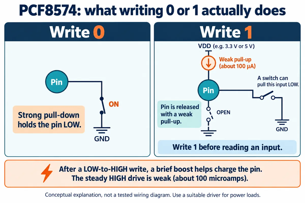
Writing zero pulls a pin low; writing one releases it with a weak high so an external switch can pull it down. An input has to be released before it is read. These behaviors come from the NXP PCF8574 data sheet.
That weak high matters. An expander pin is not a power supply. A bare LED needs current limiting and the right connection; larger loads need a proper driver. We used an LED module, so our result does not show how a bare LED or a relay should be wired. Adafruit's PCF8574 guide has a separate button-and-LED example that calls for an LED resistor, on different hardware.
A wrapper that makes groups of pins easier to address can have side effects. A read-all function that briefly releases every pin before reading also releases pins used as outputs, and a port-state function may return configured defaults rather than live readings. Check behavior like this before combining input scanning with indicators that must stay steady. Also check the carrier's supply selector and measure the actual rail voltage rather than relying on a schematic label.
Decide how the finished panel should behave
Both examples polled: the controller asked for the current inputs repeatedly. That can suit human-operated controls, but polling schedule, other bus traffic and application code set the responsiveness, so measure worst-case response time on the real build.
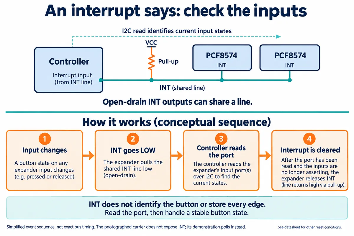
Both chips can raise an interrupt when an input changes. That notification is not a complete button event and does not keep every fast transition. Neither of our carriers brings out its interrupt pin, so using it would need a different connection or board.
For a small panel, the next test should answer:
- Does one press produce one action, including slow presses and long holds?
- Do simultaneous controls work while a display and other I2C devices are busy?
- Do indicators start in the intended state after power-up and reset?
- Does the final cable routing in the enclosure keep communication reliable?
If several expanders are needed, assign their addresses deliberately. A scan shows which addresses respond, not which part is which.
Keep the controller, or change it for a reason
An expander is reasonable when the shortage is a handful of ordinary digital signals and the existing controller otherwise suits the product. It is less convincing when the real need is fast edge capture, analog measurement or load power; more digital pins solve the wrong problem there.
Before ordering hardware for a whole panel, map each user control to its chip signal, voltage, software behavior and connector. Check the licenses of any libraries you plan to ship in the product as well. Then build from a known electrical state to a visible interaction, and test that interaction in the product people will actually hold.