
You connect a microphone, speak near it and see SOUND! on the screen. That is encouraging when you are building a voice-controlled object, an audio toy or an interactive exhibit. Before choosing the next feature, check what the program actually captured: a threshold crossing, a recording and a recognized word need very different amounts of information.
On our bench we connected a MAX9814 microphone amplifier on a GraftSense carrier to the analog input of a Raspberry Pi Pico running MicroPython, and printed readings whenever they crossed a threshold. Here is what that shows, and what has to come next if the product needs usable audio.
Start with what comes out of the microphone
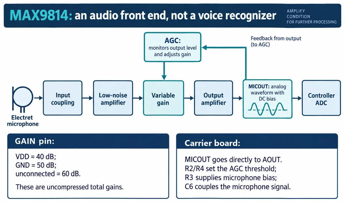
The electret microphone converts sound into a small electrical signal. The MAX9814 amplifies it and provides an analog output for the controller's ADC, which turns voltage into numbers. There is no speech recognition inside this amplifier.
The output carries a DC bias: the waveform swings above and below a positive resting voltage, not around zero. The MAX9814 data sheet gives a nominal unloaded output bias of 1.23 V. A sizable ADC reading in a quiet room can therefore be normal; it is not evidence of loud sound.
We used the carrier's analog connector into GP26. On this carrier, MICOUT connects directly to AOUT, so the bias reaches the ADC. Check the output range against the controller's input limits when moving to another board; supply voltage and signal voltage are separate questions.
The carrier's other signal line controls gain; it is not a digital audio stream. Our gain-control examples had conflicting pin assignments, and their "high" and "low" labels did not match the chip's gain order, so our default test left gain control out. Follow the actual board mapping before adding it.
What the threshold test actually does
Our program created an ADC on GP26 and passed it to the microphone driver. In its default mode it:
- took 200 quick readings and averaged them as a baseline;
- set the threshold to that baseline plus 5000 counts;
- read one value for a
Currentfield; - checked up to ten new samples for a threshold crossing;
- if triggered, took twenty more samples and reported the largest as
Peak; - waited 0.6 seconds and started again.
Current and Peak come from different samples. Nothing records a continuous waveform, and gaps of over half a second cannot reconstruct speech. The baseline is an average of the biased electrical signal, not a calibrated room-noise level.
The terminal showed one Silent line followed by repeated SOUND! lines, including a full-scale reading of 65535 and later values around 24,000. We had no waveform and no known acoustic stimulus, so the cause of that full-scale sample is unknown, and it needs investigation before you trust the signal range. What we demonstrated is a running input-and-threshold test, not an intelligible recording.
Understand what automatic gain changes
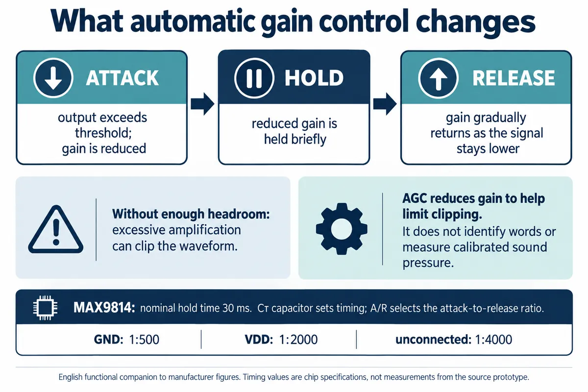
Automatic gain control (AGC) reduces amplification when the output exceeds a threshold and restores it over time as the signal gets quieter. That helps when a speaker moves closer, but it also means twice the output amplitude does not mean twice the sound level.
Gain does not change instantly either way. The chip has attack, hold and release behavior, set by an external capacitor and a configuration pin. These settings affect how the output behaves after a loud sound. We did not measure that timing or compare settings.
For a product that only needs a playful reaction to sound, a carefully tested level estimate may be enough. For a recorder or voice feature, the question is whether the whole audio path preserves the information the next stage needs. Changing an AGC setting does not supply a missing capture buffer, sample timing or recognition software.
Capture one listenable sample before adding recognition
A 2023 Edge Impulse forum thread describes a close relative of this problem: a Pico and MAX9814 always returned the same classification even though the model worked in the browser. The support reply started by asking the author to listen to a captured frame. The thread did not end with a confirmed fix, but the order of work is right: check the input before blaming the model.
A Zephyr recording discussion on GitHub describes ten seconds of capture playing back in about two. The posted code read, wrote to storage and slept in the same loop, and a reply pointed to the accumulated timing overhead.
For the next version, choose the audio format the intended recorder or recognition system needs. Sample at a controlled rate into a buffer, keep storage writes and terminal printing from disturbing that rate, and save the recording with the correct sample count and format. None of that is in our threshold test.
For scale: 16,000 samples per second means one sample every 62.5 microseconds. That is a very different job from taking a few readings and sleeping for 0.6 seconds. The right rate depends on the task and software; the arithmetic only shows the timing demand.
Listen to a short recording of ordinary speech from the intended distance. Check its duration, whether the words are intelligible, and whether the waveform clips or has gaps. If it fails, fix acquisition before training or tuning recognition. If it passes, use that same captured input when comparing later processing stages.
Repeat the check with the enclosure in place
A microphone that works in the open may pick up muffled speech, vibration or internal reflections once assembled. Include the intended sound opening, microphone position and any nearby speaker in the next prototype, and compare the same spoken phrase with the board exposed and with the enclosure fitted.
Seeed's ReSpeaker enclosure guidance covers acoustic access and speaker vibration for its own voice kit. Its two-microphone geometry is different from this single-microphone carrier, but it shows why the enclosure belongs in audio testing rather than being added at the end.
The useful milestone is not more SOUND! messages. It is knowing which stage you have reached: electrical input, a usable recording, or recognition tested with the intended voice and environment. Our test covers the first. A short, repeatable recording test is the concrete next step. If you reuse the driver we used, note that it carries a noncommercial license.