
A custom knob can make a small instrument, desk controller or interactive exhibit feel more approachable. With a magnetic angle sensor, the moving part carries a magnet while the electronics read its position without a sliding electrical contact. That gives you another way to arrange the control inside an enclosure.
It also creates a mechanical task that is easy to underestimate: the magnet must rotate in the right place relative to the sensor. A terminal full of degree readings does not prove that the knob is correctly assembled, or even that the software has checked for a usable magnetic field.
On our bench we connected a GraftSense AS5600L magnetic angle module to a GraftPort-RP2040 board running MicroPython, installed a driver and recorded readings with a magnet nearby. This note separates what that test showed from what a finished magnetic knob still needs.
Design the magnet and the mounting together
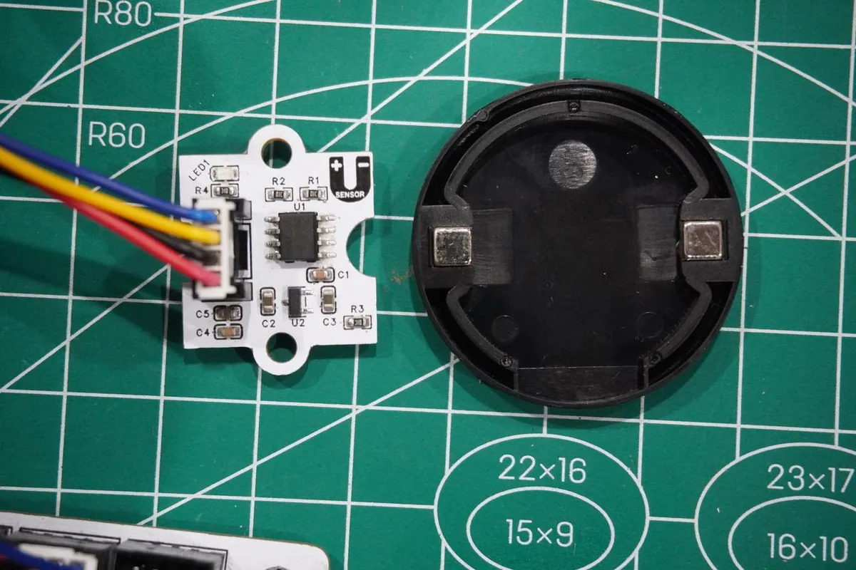
The AS5600L measures the angle of a rotating magnetic field. Its intended arrangement is a diametrically magnetized magnet centered on the rotation axis above the chip. "Diametrically" means the poles lie across the magnet's diameter; a common disc magnet with poles on its two flat faces is a different arrangement.
This comes up in real builds. In an October 2022 SimpleFOC discussion, a beginner saw unexpected direction-dependent readings, and the reply questioned the magnet type. The thread does not show a confirmed fix, but it shows why changing code should not be the first response to every strange angle.
For a knob, the bearing or shaft support decides whether the magnet stays centered as the user turns and presses it. The board position decides the gap. Prototype the two together, with the actual enclosure thickness and fasteners, rather than testing with a magnet held loosely by hand.
The AS5600L datasheet describes alignment and gain-based gap adjustment. Its reference dimensions apply to specified magnets; they are not a spacing rule for every magnet or surrounding material. Check signal validity through a full turn in your own assembly.
Reproduce the electrical connection first
We used I2C0 with GP4 for SDA and GP5 for SCL. The module is an AS5600L, whose default seven-bit address is 0x40; examples for the plain AS5600 commonly use 0x36. Similar names are not a reason to swap addresses or assume every configuration feature matches.
The host and module also need compatible power and signal levels. Follow the module's own circuit and connector labels. A datasheet showing both 5 V and 3.3 V chip supply arrangements does not make every breakout interchangeable.
Our test program scanned the bus, created a sensor object with an AS5600L driver package (version 1.0.0) and printed the raw angle, a processed angle and a magnet flag about once a second. That is a bench diagnostic, not an update-rate test for an interactive knob.
The 12-bit angle uses 4,096 positions per revolution, so an unscaled count converts to degrees as count * 360 / 4096. One count is about 0.088 degrees, but mechanical alignment, sensor error and processing all affect the real result. Digital resolution is not a measured accuracy for this build.
Read the recorded result, and its limits
The terminal found a device at 0x40 and showed changing angle values. It also printed magnet=0 on every line, including lines with nonzero angles, and several readings sat at zero or near 359.91 degrees. The output does not support a conclusion that the magnet was detected correctly.
Checking the driver against the manufacturer's register table explains why the flag cannot be trusted. The driver read its "status" from register 0x1B, but the actual STATUS register is 0x0B; 0x1B is where the magnitude value starts. So the printed flag was not the magnet-detected bit at all.
That is a specific software defect, not proof that the magnet is absent or unsuitable, and it does not explain every angle jump. Correct the diagnostic and repeat the test before deciding whether the problem is the magnet, its mounting or something else.
Check validity before using an angle
Here is a read-only diagnostic for the pins and default address above. It reads the correct status register and then the two raw-angle bytes. We checked it against the documented register layout; we have not run it on our hardware yet.
from machine import I2C, Pin

bus = I2C(0, sda=Pin(4), scl=Pin(5), freq=100_000)
address = 0x40
status = bus.readfrom_mem(address, 0x0B, 1)[0]
detected = bool(status & 0x20)
weak = bool(status & 0x10)
strong = bool(status & 0x08)
print("detected:", detected, "weak:", weak, "strong:", strong)

if detected and not weak and not strong:
    data = bus.readfrom_mem(address, 0x0C, 2)
    raw = ((data[0] & 0x0F) << 8) | data[1]
    print("raw angle:", raw * 360.0 / 4096.0)
else:
    print("Do not use this sample as a knob position")
This is a first gate, not an accuracy test. In a finished control, decide what the interface should do when the magnet becomes unreadable. Holding the last valid setting and showing a fault is often better than suddenly setting a parameter to zero. Choose the behavior for the application and test it on purpose.
For a first test, leave permanent programming alone. The driver we used also had discrepancies in its configuration and burn commands, so its programming helpers are not a commissioning procedure. Reading position does not require permanently programming a custom range.
Make direction and wraparound behave naturally
The module's DIR selection decides whether the count increases clockwise or counterclockwise.
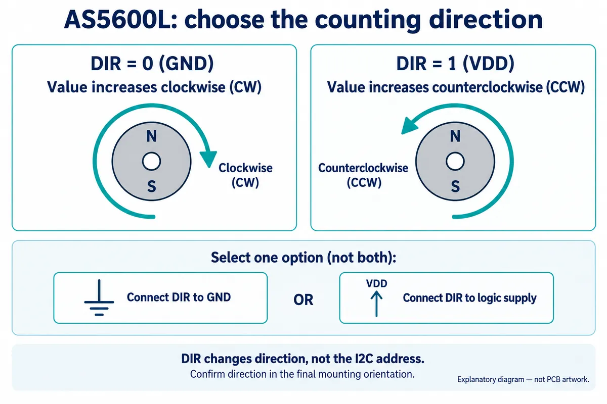
Test the assembled knob from the user's side. Turning clockwise should do what the interface promises, whichever way the sensor faces inside the case. Check a full revolution in both directions, paying particular attention to the boundary between the highest count and zero.
Those two values are neighbors on a circle. A naive subtraction can make a tiny movement across the boundary look like almost a full turn in reverse. A relative control needs wraparound handling; a control with physical end stops needs a defined usable range. Our once-a-second print loop demonstrated neither.
Finally, repeat the test while pressing the knob, with the enclosure cover on, and with nearby magnetic parts in their intended positions. Record both angle and validity, and compare the response at known mechanical positions. That separates a sensor that communicates from a control that people can use consistently.
For a first product prototype, the milestone is a dependable interaction: the knob turns smoothly, the displayed setting follows predictably, and a missing or displaced magnet produces an intentional response rather than a surprise.