
The interface for your controller looks convincing in the simulator. On the first physical unit, the blue button turns red, or small text has colored edges. Before asking your designer to change the palette, or ordering another display, check how the prototype sends colors to the panel.
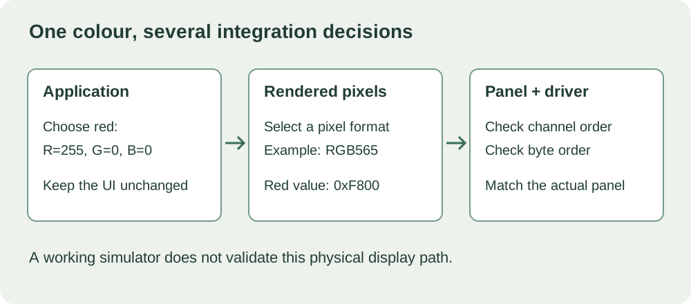
For a team moving from an on-screen demo to a working enclosure, this is a useful boundary to understand. The application chooses a color; a display driver turns that choice into pixel data the panel can read. A mistake between those steps can affect every screen, even when the artwork is correct.
Start with a small test page of labeled color blocks. Keep the interface artwork unchanged while you find which part of the path is responsible.
What the color API tells you, and what it does not
LVGL creates colors from red, green and blue values. In C, lv_color_make(255, 0, 0) gives red and lv_color_hex(0x0000FF) gives blue. A MicroPython binding may expose these differently.
In the LVGL 9.0 color implementation, the color object has three eight-bit channels. That does not mean every connected display receives three bytes per pixel. The object's fields and the display's transmitted pixel format serve different purposes.
Reading the API declarations tells you how the application describes a color. It does not tell you the order in which a display driver transmits pixels, and it cannot establish that a particular panel is configured correctly. The simulator also cannot verify the wiring and transfer configuration of hardware it is not driving.
Two changes that sound similar but do different things
RGB and BGR describe the arrangement of color channels. If red and blue trade places while green stays correct, channel order is worth checking. It is a clue, not a diagnosis: confirm the panel configuration and a known test pattern before changing anything.
RGB565 byte order is a separate issue. This format packs a pixel into 16 bits: five for red, six for green and five for blue. Full red is the value 0xF800. Transmitting its two bytes as F8 00 or 00 F8 changes what the receiving panel interprets. Swapping those bytes is not the same operation as exchanging red and blue channels.

The LVGL 9.0 display porting documentation distinguishes the two explicitly. It describes a byte-swap helper for RGB565 when the transfer path needs it. Whether a particular driver already handles that step must be checked before adding another conversion.
A November 2022 LVGL forum report makes the distinction concrete. The author described reversed red and blue on an older parallel-display setup; changing a byte-swap option did not solve it. They later reported a channel-conversion workaround. That workaround is not a recipe for a different board or LVGL version, but the report shows why the symptom deserves investigation instead of a guess.
Give the developer a repeatable test, not a different palette
Use a page with labeled red, green, blue, black and white blocks, followed by a few intermediate colors and a short line of text. Write the intended values beside the labels. Black and white are useful checks, but their RGB565 values, 0x0000 and 0xFFFF, look unchanged after a byte reversal. A black-and-white screen can therefore hide this fault.
Run the same pattern through the panel driver's simplest supported drawing example, then through LVGL. If the direct example is also wrong, investigate the panel setup and transfer path first. If it is correct and LVGL differs, compare the format and conversion steps between the two paths. This comparison narrows the search; it does not prove that either library is defective.
Record one change at a time, with the same displayed pattern. Keep the panel model, board, firmware revision, LVGL version and driver configuration with each photograph. A phone photo is fine for spotting an obvious channel reversal, but automatic exposure and white balance make it unsuitable as a color-calibration measurement.
Fix the integration before approving the screen design
Establish where the pixel format is selected and where any byte or channel conversion happens. LVGL 9.0's display header provides lv_display_set_color_format for the display format. The panel's own configuration and the transport driver still have to match it. Copying an option from an LVGL 8 example or an unrelated framework can change the wrong layer.
Once the basic pattern is correct, return to the real interface. Review icons, gradients, small text and disabled states on the physical unit. A passing pattern is a useful integration checkpoint, not proof of accurate color reproduction, outdoor readability or readiness for production.
For the next engineering handoff, send the unchanged UI, the labeled pattern, the observed result and the versioned display setup. That gives the next engineer a reproducible problem instead of a request to "make the colors look right."