
Your prototype's LED matrix runs a colorful animation, but the small arrow you draw points the wrong way. Or a color you meant as a warning looks blue. For a designer building an interactive object or a small status display, these are practical problems: the lights work, yet the message does not.
A useful next step is to make position and color predictable before adding more animation. On our bench we drove a GraftSense 8 × 8 WS2812 matrix module from a GraftPort carrier with a Raspberry Pi Pico, running MicroPython, and recorded the light sequence. This note covers what that run showed and what a display still needs before someone can use it without an explanation.
Decide what one small picture should say
Start with one message, such as "waiting for input" or "task finished." A simple shape is a better first test than a scrolling sentence. You can then ask whether the shape appears in the intended orientation and whether someone understands it at the distance where the product will be used.
The gap between software coordinates and the real display is easy to miss. In an October 2023 WLED discussion, a builder reported that a text preview looked right while the physical matrix showed unreadable, vertically wrapped text. The cause turned out to be mixed-up X/Y coordinates and the direction of the serpentine layout. That is one configuration problem, not a fault in every matrix, but it is a common one.
A grid on the front, a chain underneath
Although the board looks like a grid, its LEDs receive data in sequence. The controller sends the first pixel's color data, then the second pixel's, and so on. Each LED keeps its own data and passes the rest along. The driver must translate a drawing coordinate, such as column 2, row 3, into the right position in that chain.
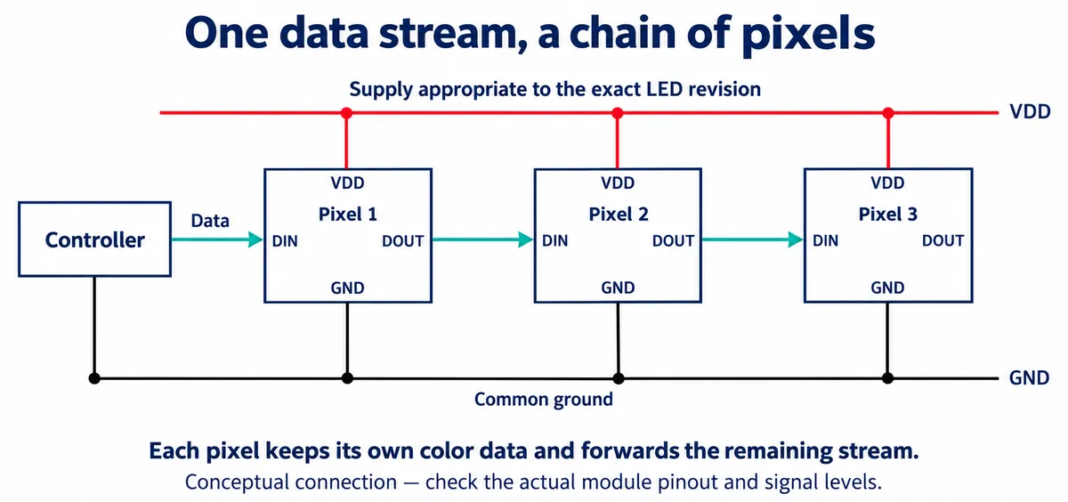
Some matrices run along each row in the same direction. Others reverse direction on alternate rows, often called a serpentine or zigzag layout. Turning the board changes where its first pixel appears to the viewer. Adafruit's NeoMatrix guide explains these layouts clearly; its Arduino settings are not interchangeable with the MicroPython driver we used.
We connected the matrix's data input to GP6 through the carrier's DIO0 connector; the neighboring GP7 position was unused. That assignment belongs to this setup. Another carrier may put different signals or voltages on a similar-looking connector.
Check power before copying the arrangement
Check the board revision and power connection before copying the setup. The reference material for this module mixes several LED packages, and its power descriptions are not consistent. A successful low-brightness animation does not establish a maximum current rating. For an enclosed prototype, measure the actual board with the brightest patterns you intend to show, and confirm that the supply, cable and connector can carry them. Software brightness is not a substitute for that check.
Configuration: layout, flip and color order
We used our own matrix driver package. Record the exact driver file with your project: its package metadata said 1.0.0 while the file header said 0.1.0, and labels alone will not tell the next person which code produced your result.
The program configured an 8 × 8 matrix on GP6 with a row layout (every row progresses in the same direction), a brightness of 0.2, a BRG color-order setting and a vertical flip. The flip reverses the vertical coordinate before the pixel index is calculated. In this driver, logical coordinate (0, 0) therefore maps to chain index 56, while (0, 7) maps to index 0. We checked those results in software. They do not tell you which corner ends up on top once the board is mounted.
The color-order setting needs its own test. The driver rearranges the color tuple before passing it to MicroPython's NeoPixel object, so copying an option name from a different library will not necessarily give the same result. Show red, green and blue separately at low brightness, check them by eye and record the setting that works with your firmware and module.
What the recorded run showed
The test program first filled the display one pixel at a time, then drew and moved horizontal and vertical lines. Our recording shows the matrix lighting progressively and displaying moving colored bands. That shows this setup can update the LEDs. It does not establish color accuracy, text readability or behavior inside an enclosure; camera exposure and the color-order setting also mean the video is not a color reference.
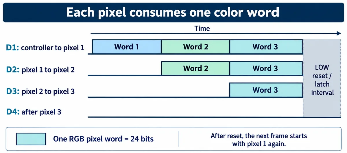
Two details from the program are worth keeping. Drawing changes the image held in memory; show() sends that image to the LEDs. And scrolling can either clear newly exposed pixels or wrap pixels around to the other side; the program demonstrated both. For a status symbol, choose deliberately, because a leftover pixel or a wrapped edge changes the apparent shape.
The driver also has helpers for loading images and playing frames at a target of 30 frames per second, but our test sequence did not call them. A target in code is not a measured frame rate. If animation must stay smooth while the prototype reads sensors or receives messages, test those tasks together.
Make a small, repeatable display check
Once the basic sequence runs, simplify it. Light one corner, then the next, in an unmistakable order. Follow with one full row and one full column. If either appears somewhere unexpected, fix the layout or orientation settings before touching the artwork. A symmetric square can hide a mirrored or rotated image.
Next, show the same asymmetric symbol in each primary color. Keep a photo and the configuration beside the artwork so a later assembly can reproduce the result.
Finally, place the matrix behind the intended front panel. Check it from the expected distance and under the intended room lighting. A cover that softens the pixels may also merge neighboring points, so a symbol that is clear on a bare board can lose its shape. Show the actual message to someone who has not watched you build it, and ask what they think it means before you explain.
If the pixels are in the right places but the meaning is still unclear, change the symbol or the display approach. Faster animation will not fix an ambiguous message. A small matrix is a good way to explore expressive shapes; a product that must show detailed instructions may need a different display.
Bring the display and the enclosure into the same prototype
Our run established a working path from drawing commands to a physical panel. The next milestone is a repeatable combination of board orientation, color settings, artwork, brightness and front-panel material that communicates one intended message.