
You press a button on a small controller and its screen changes. That feels like success, until the lamp, display or interactive object across the room does nothing. For a team building a physical remote, the useful question is not only "Can we send a command?" It is "What can the user actually know happened?"
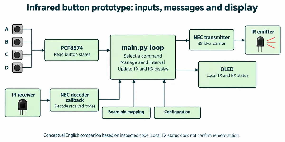
On our bench we built two units from the same parts list: four buttons, an infrared transmitter and receiver, and a small OLED on a GraftPort controller board with a Raspberry Pi Pico running MicroPython. The firmware maps each button to a letter and shows local transmit (TX) and receive (RX) activity on the screen. It is a good setup for separating three different events: a button press, a transmitted message and a confirmed action.
It is not a finished remote for a commercial appliance. The address settings and error handling in the test firmware also needed attention, which is a large part of what this note is about.
Why the feedback question matters
A small physical controller could select a scene in an exhibit, trigger an interaction in a classroom or change a setting without opening a phone. Those are possible uses of a few clear commands; we have not deployed this build for any of them.
The need for feedback shows up in real user discussions. In a PIXBOOM camera-control thread, users asked for a visible recording indicator on a remote and for different start and stop beeps. That is a different product and link, but the question transfers: how do I confirm the equipment is doing what I asked?
In our test firmware, TX is local information: the program called the transmit routine. RX is received data shown after the application's filtering. Neither label confirms that a remote device performed the requested action. If that confirmation matters, the next version needs an explicit response tied to the command, or an effect the user can see at the target.
How the controller is wired
| Function | Connection |
|---|---|
| PCF8574 I/O expander for the buttons | I2C0, address 0x27 |
| Four mechanical buttons | Expander inputs used by the firmware map |
| IR333C-based transmitter module | DIO0 |
| TSOP34138-based receiver module | DIO1 |
| SSD1306 OLED | I2C1, address 0x3D |
The buttons go through an I2C expander instead of four direct inputs. The firmware maps expander bits 0, 2, 5 and 7 to command indices zero through three and shows them as letters a through d. Match the physical wiring to that map; plugging four buttons into arbitrary expander sockets is not enough. The code expects fixed addresses for the expander and the display and does not try a second common OLED address, so confirm the actual addresses on your modules.
The loop picks one index per pass. It does not define a chord or send several pressed buttons as a group. A product should either define simultaneous presses on purpose or make them harmless.
The link uses NEC encoding on a 38 kHz carrier, with an NEC decoder on the receive side. The transmitter and receiver need a clear optical path. We did not measure operating range or angle, so nothing here supports a claim that the remote works anywhere in a room.
Enclosure and power checks
The parts are mounted on a perforated base with M3 spacers and screws and closed with acrylic panels. Before committing to a new case, try the button positions and the screen viewing angle with the optical modules in place. A case that looks right from the front can still block the transmitter or leave the receiver facing away from the user.
The power cable we used is marked with red to GND and black to VCC, the reverse of the usual convention. Check the actual cable and connector polarity rather than trusting wire color. A battery indicator and a lit board LED help during setup, but they do not prove the infrared path works. Check power, local button input and received data as separate steps.
Understand the sending cadence before changing it
The main loop reads the expander, selects a command and sends only when more than three seconds have passed since the previous send. That is a periodic demonstration, not one message per press. A short press can fall between checks, and a held button can produce repeated sends.
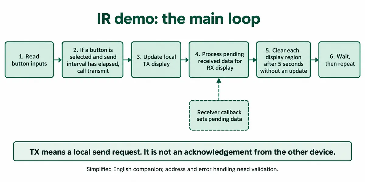
After a transmit call, a pending flag tells the loop to update the TX area of the screen. Received data reaches the RX area through a callback and a second pending flag. Each area clears after five seconds without an update. Clearing the text is display housekeeping, not a command timeout and not evidence that a link has failed.
A held button needs a product decision. Repeating "increase brightness" can be useful; repeating a toggle can undo the first press. An Arduino Forum reply from November 2018 discusses that distinction for a radio remote. It is useful interface context, not a validation of this infrared driver. For a first user trial, choose one behavior per button and make it visible. If each press should trigger exactly one change, record press and release explicitly instead of relying on a three-second interval.
Resolve the address and error cases first
The main file we tested sends to address 0x00 but only displays received data from address 0x01. Two identical copies of that file therefore do not give a symmetric two-way exchange, even though two assembled units side by side suggest one. Record the intended address of each unit and check which firmware version is actually on each.
Our terminal log showed received addresses, commands, local sent letters and pending received letters. It also included a negative command value, printed as 0x-2, which is not one of the intended commands zero through three. The receive callback maps the command with modulo four after its address check, so a bad value can still turn into a valid-looking letter. The callback's third argument is named repeat, but the decoder we used passes zero in that position. That code does not prove that repeated frames and decode errors are filtered. Validate the decoded command before converting it to a letter, and test the specific driver version you ship.
The log and the firmware we inspected were not one reconciled two-unit test record. Treat the exchange we saw as a working assembly, not as evidence of error-free delivery, operating range or compatibility with other remotes.
Make the next test prove one message
Start with one button and one known command. Record the sender's selected index, the transmitted address, the receiver's decoded address and command, and what the receiving application did. Then try a short press, a held press, a second button and a blocked optical path. Add enclosure and ambient-light variations once the basic mapping is understood.
If the application needs confirmation at the controller, define what counts as success. "Message decoded" and "requested scene applied" are different responses. A sequence number and a bounded wait for a reply are possible additions; we have not implemented or tested them.
The useful outcome of a first trial is a small, explainable command set. The person pressing the button should be able to tell whether the device is sending, waiting or showing a confirmed result. That is a better base for the next enclosure revision than adding more buttons.