
You connect a sensor, run an I2C scan and see the expected address. It feels like the hard part is over. Then the driver returns zeros, an implausible value or an error. For a team assembling its first sensor-based product, the useful question is what the scan actually proved, and which part of the conversation still needs checking.
A scan is an address probe. It does not ask the sensor to make your measurement, check the conversion formula or confirm that the driver matches the fitted component. Treat it as a useful first step, then follow one documented read from the request to the returned bytes. This note walks through that conversation using protocol diagrams, not captures from a particular sensor; read it next to your module's datasheet.
Keep the device address separate from the value you want
The device address chooses which component to talk to. A register address chooses a location inside that component. They are different numbers with different jobs. Some devices accept commands and return a response instead, so a register-style read is not right for every sensor.
In MicroPython, scan() returns responding 7-bit addresses. The probe checks whether a device acknowledges its address with the write direction. If a datasheet lists separate write and read address bytes, do not copy either one into a function that expects the seven-bit address.
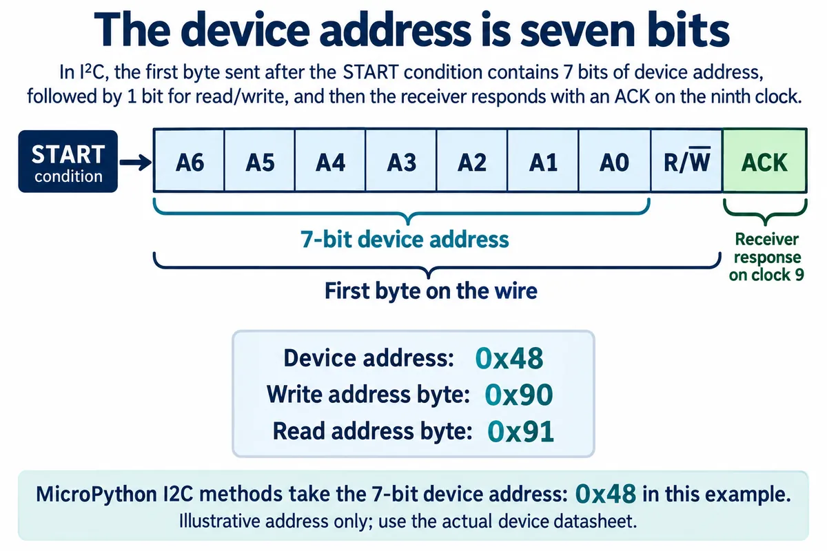
With an illustrative device address of 0x48, the address byte on the wire is 0x90 for writing and 0x91 for reading. Those are not three different sensors. Use your module's actual address configuration; this is not an address recommendation.
Next, identify the register or command you need, the expected response length and any required initialization. If the part has a readable identity register, that makes a good first transaction; check the expected value in its own datasheet. A successful identity read is still a communication check, not a calibrated measurement.
A register read may begin with a write
In a write, the controller selects a target and sends it bytes. Those bytes have no universal meaning: a device might treat them as a register pointer, a configuration value or a command. The right device address followed by the wrong bytes reaches the correct chip and still requests the wrong operation.
In a common register-read pattern, the controller first writes the register location, then switches direction to receive its contents. Whether a STOP is allowed between those phases depends on the target. A repeated START begins the next phase without ending the transaction. Adafruit's repeated-START guide explains why some devices depend on that distinction.
In MicroPython, readfrom_mem(addr, memaddr, nbytes) is meant for memory or register access. Its addrsize option describes the width of the internal memory address, not the device's bus address. For a command-based part, follow its command sequence instead. Check the documentation for the firmware you actually run rather than assuming every I2C method fits every device.
Know who sends each acknowledgement
When the direction changes, the controller receives the requested bytes, and its own response tells the target whether to continue. So reading a capture means knowing which phase you are looking at, rather than treating every response as something the sensor sent.
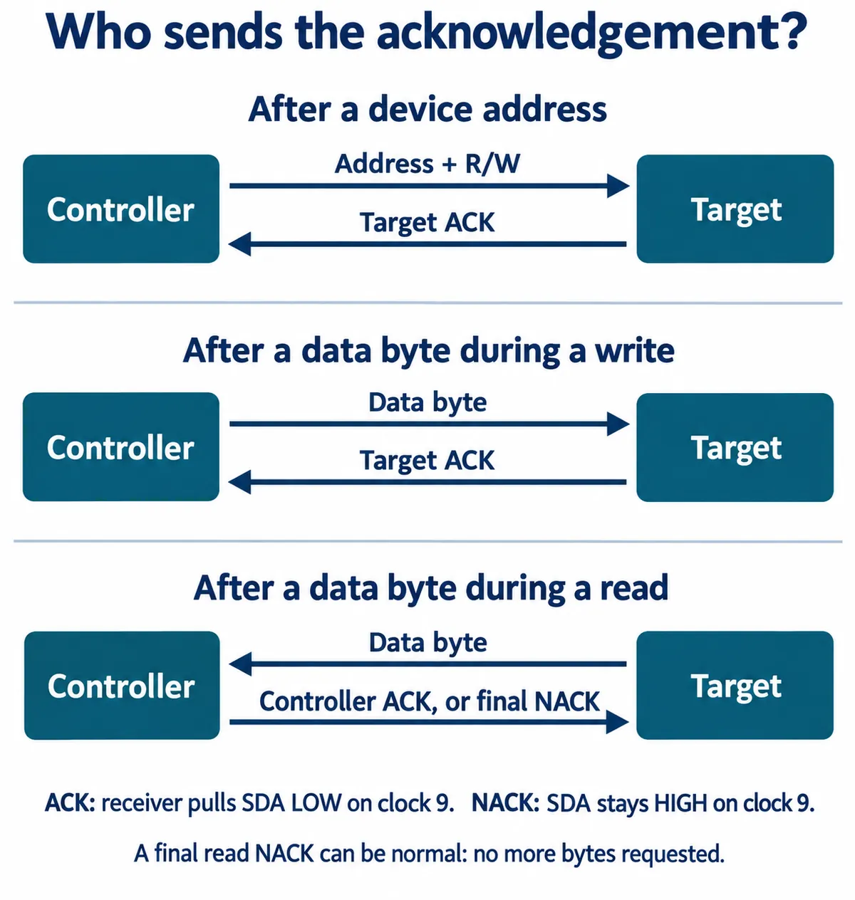
That is why the last NACK in a successful read is not a failure. When reviewing a decoded capture, ask where the NACK appears and which side sent it. A refusal after an address or a written byte means something different from the controller deliberately ending a read.
Acknowledgement is part of each byte transfer. It does not certify that a measurement is accurate or that a physical action has finished. "Write completed" and "the sensor produced a new valid reading" are different events and should be logged as such.
Compare a failing conversation with a working one
A September 2026 ST Community question shows why this matters. An ISM330DHCX user reported sometimes reading the expected identity value and sometimes getting a different value or a failure. Shortening the wires did not fix it. The visible discussion recommended checking signal quality and comparing decoded working and failing transactions; it did not establish a final cause.
For your own prototype, capture one minimal request before adding the screen, logger and other sensors back into the program. Record the device address, bytes sent, response length, returned bytes and any error. A logic analyzer shows whether the transaction matches the documented sequence; an oscilloscope answers a different question about the electrical signals. Ask for both when intermittent behavior stays unexplained.
A target can also hold SCL low while it needs more time, which is called clock stretching. Support and timeout behavior depend on the controller and firmware, so adding a delay in the application is not a substitute for understanding the transaction.
If modules work separately but fail when combined, check shared-bus loading too. A correct command sequence cannot make up for an unreliable electrical connection, and changing pull-ups will not fix a register address copied from a different chip's driver.
Keep the raw bytes until the reading makes sense
Once a transfer succeeds, there is still decoding to do. The sensor may pack signed values, status bits or several bytes into its response, and its datasheet defines the order and meaning. I2C sends the most significant bit of each byte first, but that says nothing about the order of bytes in a multi-byte measurement.
As arithmetic only: bytes 0x01, 0x00 are 256 if the first byte is the high byte, and 1 if it is the low byte. Neither is justified until you know the device's format. Scaling either number into a plausible unit can hide the mistake instead of fixing it.
Keep a short raw record beside the converted output. Change one known input condition and check that the value moves in the expected direction. Repeat after reset using the documented initialization and readiness rules. These are proposed checks; protocol diagrams and forum replies cannot supply those measurements for your particular module.
Bring a small, reproducible question to the next review
The most useful hand-over is the exact module identification, firmware and driver revision, the relevant datasheet page, the minimal request and the raw response. Add a photo of the connections and a working and a failing capture when you have them. That gives the next engineer something concrete to compare, instead of a folder of several unrelated "working" drivers, and it narrows the next step to communication, device setup or interpretation before anyone replaces parts.